Power output device and equipment

A power output and piston technology, applied in the field of power output equipment, can solve the problem that the output shaft cannot stop accurately

Pending Publication Date: 2019-07-12
李纪友
View PDF0 Cites 0 Cited by
  • Summary
  • Abstract
  • Description
  • Claims
  • Application Information

AI Technical Summary

Problems solved by technology

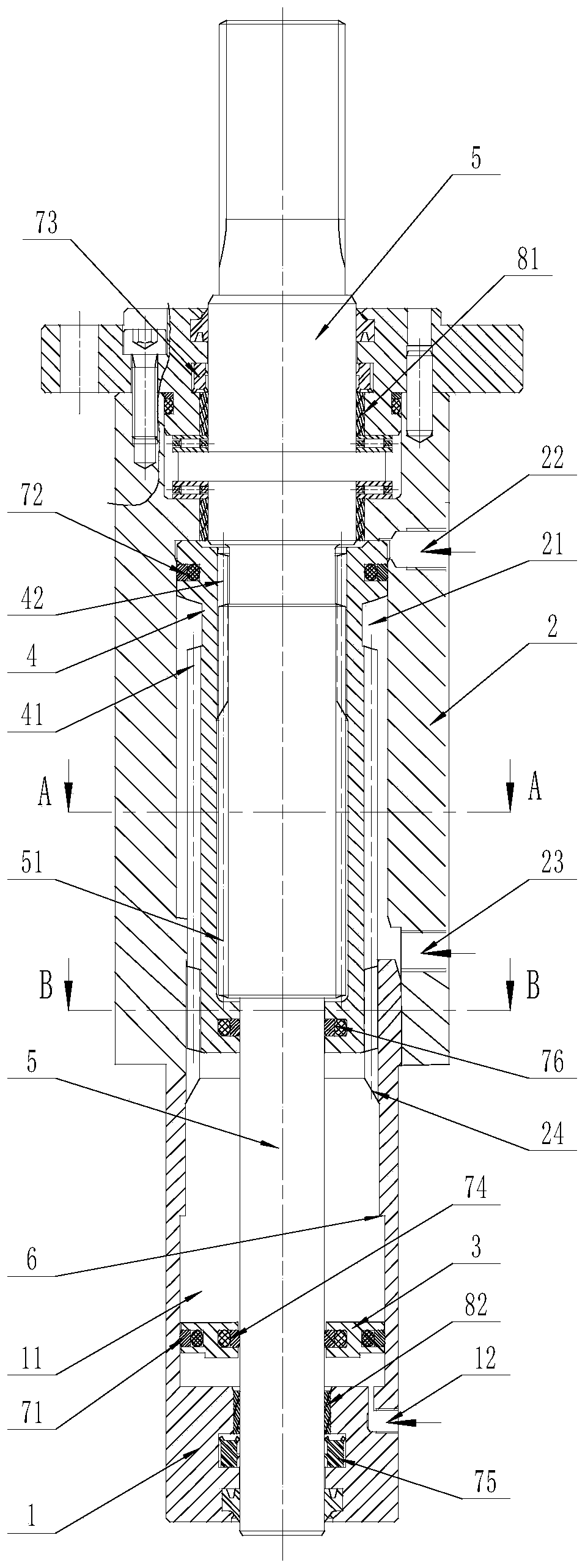
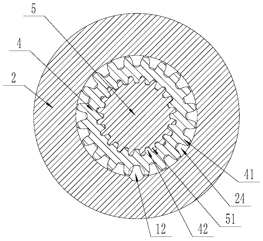
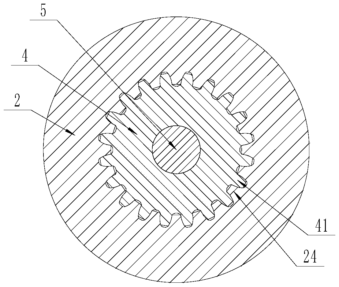
[0005] In order to solve the above-mentioned problems in the prior art, that is, to solve the problem that the output shaft of the existing helical oscillating oil cylinder cannot accurately stop at a specific position in the middle of its angular stroke, the present invention provides a power output device, which The power output device includes a first housing, a second housing, a first piston, a second piston, a power output rod and a stopper structure, the first housing and the second housing are fixedly connected or integrally formed; The first housing includes a first cavity formed therein and a first channel formed thereon, one end of the first channel communicates with the first cavity, and the other end of the first channel leading to the outside of the first housing; the second housing includes a second cavity formed therein and aligned with the first cavity and a second channel formed thereon, the first One end of the second channel communicates with the second cavity, and the other end of the second channel leads to the outside of the second housing; the first piston is arranged on the first piston in an axially movable manner In a cavity; the second piston is arranged in the second cavity in an axially movable manner; the power output rod is drivingly connected with the second piston, and the power output rod can follow the The axial movement of the second piston rotates and / or moves; the stop structure is formed between the first cavity and the second cavity, and interferes with the first piston; wherein , the first channel is used to pass through the first pressure transmission medium, so that the first piston moves toward the second cavity under the action of the first pressure transmission medium and abuts against the stop structure ; The second channel is used to pass into a second pressure transmission medium, so that the second piston moves toward the first chamber under the action of the second pressure transmission medium and can selectively push the The first piston is away from the stop structure

Method used


Image

  • Power output device and equipment
  • Power output device and equipment
  • Power output device and equipment

Examples


Embodiment Construction

[0102] Those skilled in the art should understand that the embodiments in this section are only used to explain the technical principle of the present invention, and are not used to limit the protection scope of the present invention. For example, the power output device of the present invention may be a helical oscillating cylinder, a helical oscillating cylinder, a linear cylinder or a linear cylinder. Those skilled in the art can make adjustments as needed so as to adapt to specific application occasions, and the adjusted technical solution will still fall within the protection scope of the present invention.

[0103] It should be noted that, in the description of the present invention, the terms "center", "upper", "lower", "left", "right", "vertical", "horizontal", "inner", "outer" etc. Terms indicating directions or positional relationships are based on the directions or positional relationships shown in the drawings, which are merely for convenience of description, and d...


PUM


Abstract

The invention belongs to the field of power output equipment and particularly provides a power output device. The power output device aims to solve the problem that an output shaft of an existing spiral swinging oil cylinder cannot stop at the specific position of the middle of the angle stroke of the oil cylinder precisely. The power output device comprises a first shell provided with a first cavity and a first channel, a second shell provided with a second cavity and a second channel, a first piston arranged in the first cavity, a second piston arranged in the second cavity, and a power output rod in driving connection with the second piston. The diameter of the first cavity is larger than that of the second cavity, thus the second piston can slide into the first cavity, and the first piston can abut against the second shell to stop the second piston from sliding into the first cavity. According to the power output device provided with the structure, the second piston can be stoppedat the position of the middle of the stroke through the first piston, and therefore the power output rod can stay at the position accurately.

Description

technical field [0001] The invention belongs to the field of power output equipment, and specifically provides a power output device and equipment. Background technique [0002] The helical oscillating oil cylinder mainly includes a housing, a piston and an output shaft. The helical oscillating oil cylinder can convert the linear motion of the piston into the oscillating (rotating) motion of the output shaft through oblique thread engagement. Specifically, two oil holes are provided on the housing. When hydraulic oil is injected into the housing through the first oil hole, the hydraulic oil pushes the piston to move in the first direction, and the moving piston drives the output shaft to rotate clockwise; When hydraulic oil is injected into the housing through the second oil hole, the hydraulic oil pushes the piston to move in a second direction opposite to the first direction, and the moved piston drives the output shaft to rotate counterclockwise. [0003] However, the ex...

Claims


Application Information

Patent Timeline
IPC IPC(8): F15B15/06F15B15/04F15B15/20
CPCF15B15/068F15B15/04F15B15/20
Inventor 李纪友
Owner 李纪友
Why Eureka
Try Eureka