
Air supplying box capable of realizing forced cooling

A technology of forced cooling and air supply box, applied in the field of workpiece cooling, can solve the problems of adjustment of workpiece cooling requirements that cannot be different, poor cooling effect, etc., and achieve the effect of increasing the coverage area and improving the cooling effect.

Pending Publication Date: 2019-07-12
ZHEJIANG HUALI INTELLIGENT EQUIP CO LTD
View PDF6 Cites 0 Cited by
  • Summary
  • Abstract
  • Description
  • Claims
  • Application Information

AI Technical Summary

Problems solved by technology

[0003] The purpose of the present invention is to make up for the defects in the prior art, provide a forced cooling air supply box, and solve the problem that the existing forced cooling air supply box has poor cooling effect and cannot be adjusted according to different workpiece cooling requirements

Method used


Image

  • Air supplying box capable of realizing forced cooling
  • Air supplying box capable of realizing forced cooling
  • Air supplying box capable of realizing forced cooling

Examples


Embodiment Construction

[0018] The specific embodiments of the present invention will be briefly described below in conjunction with the drawings.

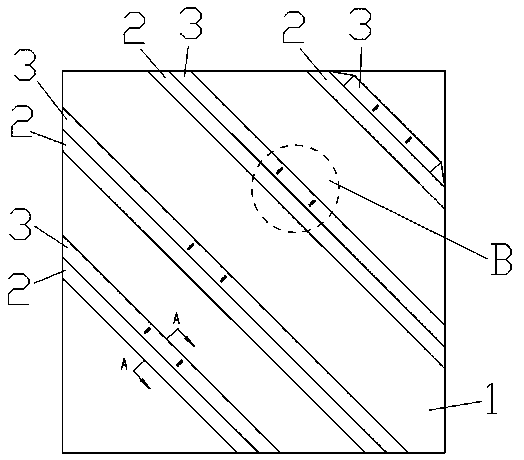
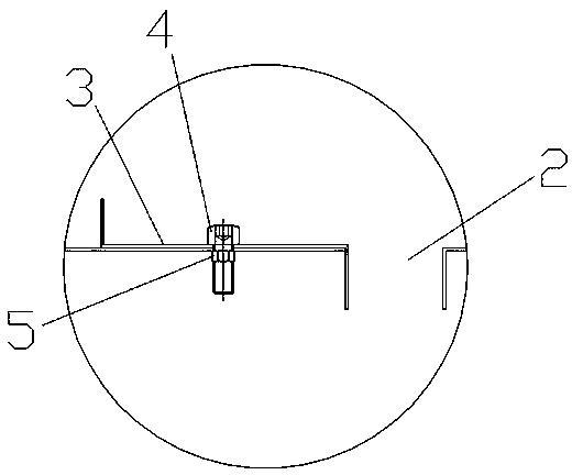
[0019] Such as Figure 1-3 As shown, a forced cooling blower box includes a blower box body 1, and the shape of the blower box body 1 can be set arbitrarily according to needs, and is preferably arranged in a rectangular parallelepiped shape. One wall of 1 is provided with a plurality of strip-shaped air outlets 2, preferably the plurality of strip-shaped air outlets 2 can be arranged parallel to each other, and the fan supplies cooling air into the air supply box 1 , The cooling air is ejected from the plurality of strip-shaped air outlets 2 to cool the batch of workpieces moving outside the air box body 1, and the preferred moving direction of the workpieces is the width direction of the strip-shaped air outlet 2 the same. It also includes a plurality of strip-shaped adjusting plates 3 respectively matched with the plurality of strip-shaped air supply o...


PUM


Abstract

The invention discloses an air supplying box capable of realizing forced cooling and relates to the field of workpiece cooling. The air supplying box comprises an air supplying box body, wherein a plurality of strip-shaped air supplying ports are formed in a wall of the air supplying box body. The air supplying box further comprises a plurality of strip-shaped adjusting plates matched with the strip-shaped air supplying ports respectively and positions of the strip-shaped adjusting plates fixed on the wall of the air supplying box body can be adjusted so that the width of the strip-shaped airsupplying ports is adjustable. With the adoption of the strip-shaped air supplying ports, one whole face of a workpiece can be blown by cooling air when the workpiece moves relative to the air supplying box in the width direction of the strip-shaped air supplying ports to be cooled, the area of the workpiece blown by the cooling air is increased, and the cooling effect of the workpiece is improved; the width of the air supplying ports can be adjusted, the air blowing area of the air supplying ports can be changed by adjusting the width of the air supplying ports, the blowing speed of the cooling air can be adjusted, and therefore, adjustment can be made to meet different cooling requirements of workpieces.

Description

Technical field [0001] The invention relates to the field of workpiece cooling, in particular to a forced cooling air supply box. Background technique [0002] The workpiece needs to be dried in the production process. After the workpiece is heated in the oven, the temperature is higher, and the workpiece needs to be cooled for safety reasons. The existing workpiece cooling method is: using a fan to provide cooling air for forced cooling of the workpiece to the air supply box, and the cooling air is ejected from the air supply opening on the wall of the air supply box, and moves to the relative air supply box outside the air supply box. The batches of workpieces are cooled, and the batches of workpieces enter the next process after cooling. However, the air outlet of the existing air supply box is a matrix of openings, so when the workpiece moves in one direction relative to the air supply box for cooling, only a plurality of strips on the workpiece can be blown by the cooling a...

Claims


Application Information

Patent Timeline
Patent Type & Authority Applications(China)
IPC IPC(8): F27D15/02
CPCF27D15/02F27M2003/025
Inventor 郎巍沈志刚沈明
Owner ZHEJIANG HUALI INTELLIGENT EQUIP CO LTD
Learn More