
Infrared target used for simulating continuous variability in laboratory and using method

An infrared target and laboratory technology, applied in radiation pyrometry, measuring devices, instruments, etc., can solve the problems of inability to simulate dynamic and variable targets, and inability to realize simulation verification of special scenes, so as to achieve effective experimental support and realization Simple, easy-to-operate effects

Inactive Publication Date: 2019-07-12
BEIJING INST OF REMOTE SENSING EQUIP
View PDF4 Cites 0 Cited by
  • Summary
  • Abstract
  • Description
  • Claims
  • Application Information

AI Technical Summary

Problems solved by technology

[0002] Infrared target is a device commonly used in sensors such as infrared imagers to simulate infrared target sources; it is generally used in conjunction with collimated light tubes to provide the required targets for infrared imagers; conventional targets are mostly fixed Targets such as point source targets, cross targets, four targets, etc., can only be used quantitatively and qualitatively, and cannot simulate dynamically variable targets; especially with the wide application of infrared technology, different simulation scenarios are required for the characteristics of the target, so , the existing technology cannot realize the simulation verification of special scenarios

Method used


Image

  • Infrared target used for simulating continuous variability in laboratory and using method
  • Infrared target used for simulating continuous variability in laboratory and using method
  • Infrared target used for simulating continuous variability in laboratory and using method

Examples


Embodiment Construction

[0014] The present invention will be described in further detail below in conjunction with the accompanying drawings and specific embodiments. According to the following description and claims, the advantages and features of the present invention will be more clear. It should be noted that all the drawings are in very simplified form and inaccurate scales, and are only used to facilitate and clearly assist the purpose of illustrating the embodiments of the present invention.

[0015] It should be noted that, in order to clearly illustrate the content of the present invention, the present invention specifically cites multiple embodiments to further explain different implementation modes of the present invention, wherein the multiple embodiments are enumerated rather than exhaustive. In addition, for the sake of brevity of description, the content mentioned in the previous embodiment is often omitted in the latter embodiment, therefore, the content not mentioned in the later embo...


PUM


Abstract

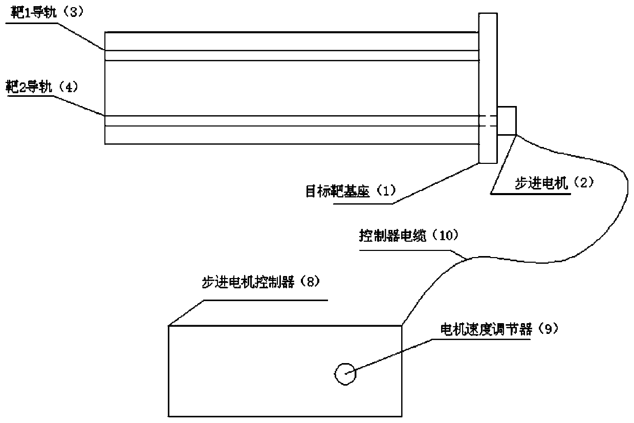
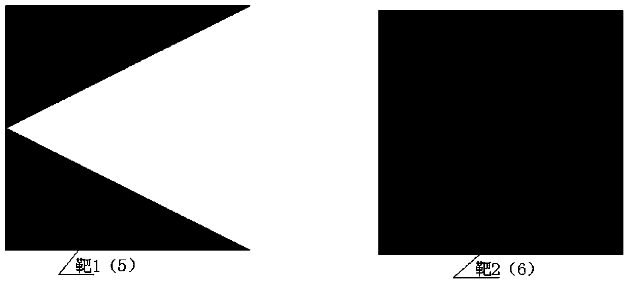
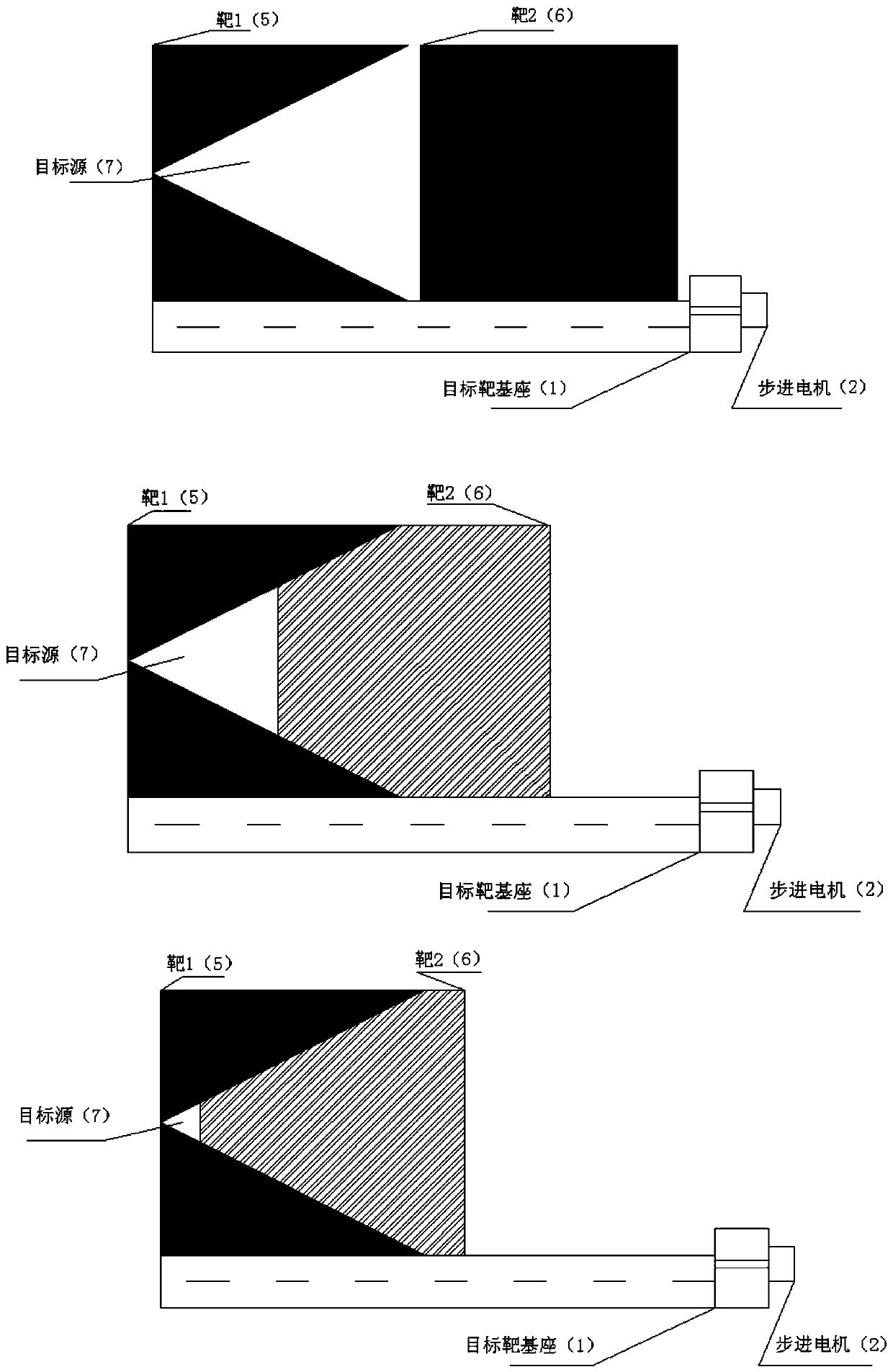
The invention discloses an infrared target used for simulating continuous variability in a laboratory and a using method. The infrared target comprises a target base (1), a stepping motor (2), a target 1 guide rail (3), a target 2 guide rail (4), a target 1 (5), a target 2 (6) and a stepping motor controller (8). The stepping motor controller (8) consists of a motor speed regulator (9) and a controller cable (10). The target 1 guide rail (3) and the target 2 guide rail (4) are fixed on the target base (1), and the stepping motor (2) is connected with the target 2 guide rail (4) through a leadscrew. The target 1 (5) is fixed on the target 1 guide rail (3), the target 2 (6) is fixed on the target 2 guide rail (4), and the stepping motor controller (8) is connected with the stepping motor (2) through the controller cable (10). The stepping motor (2) is made to move front and back by adjusting the motor speed adjuster (9) to drive the target 2 (6) to move, the target 2 (6) and the target1 (5) in the static state have relative displacement changes through movement of the target 2 (6), and the size of the target source (7) is also increased or decreased along with movement of the target 2 (6) along with the change of the displacement. According to the invention, the process of simulating an infrared target of an external field from large to small or from small to large is completedin a test room, and effective experimental support is provided for practical engineering application.

Description

technical field [0001] The invention relates to a continuously variable infrared target used for laboratory simulation and a use method thereof. Background technique [0002] Infrared target is a device commonly used in sensors such as infrared imagers to simulate infrared target sources; it is generally used in conjunction with collimated light tubes to provide the required targets for infrared imagers; conventional targets are mostly fixed Targets such as point source targets, cross targets, four targets, etc., can only be used quantitatively and qualitatively, and cannot simulate dynamically variable targets; especially with the wide application of infrared technology, different simulation scenarios are required for the characteristics of the target, so , the prior art cannot realize simulation verification of special scenarios. Contents of the invention [0003] The purpose of the present invention is to provide a continuously variable infrared target for laboratory s...

Claims


Application Information

Patent Timeline
IPC IPC(8): G01J5/00
CPCG01J5/00G01J5/80
Inventor 荆树涛温焱
Owner BEIJING INST OF REMOTE SENSING EQUIP
Learn More