
Device and method for measuring flight parameters of unmanned aerial vehicle semi-aerial transient electromagnetic receiving coil

A receiving coil and transient electromagnetic technology, which is applied in the field of flight parameter measurement device of unmanned aerial vehicle semi-aviation transient electromagnetic receiving coil, can solve the problem that the receiving coil flight parameters are not easy to measure, and achieve the reduction of self-rotation and rapid attitude change , to reduce the effect of interference

Active Publication Date: 2020-11-06
CHENGDU UNIVERSITY OF TECHNOLOGY
View PDF4 Cites 0 Cited by
  • Summary
  • Abstract
  • Description
  • Claims
  • Application Information

AI Technical Summary

Problems solved by technology

[0003] Aiming at the above-mentioned deficiencies in the prior art, a device and method for measuring the flight parameters of the semi-aviational transient electromagnetic receiving coil of the UAV provided by the present invention solves the problem that the flight parameters of the receiving coil are not easy to measure

Method used


Image

  • Device and method for measuring flight parameters of unmanned aerial vehicle semi-aerial transient electromagnetic receiving coil
  • Device and method for measuring flight parameters of unmanned aerial vehicle semi-aerial transient electromagnetic receiving coil
  • Device and method for measuring flight parameters of unmanned aerial vehicle semi-aerial transient electromagnetic receiving coil

Examples


Embodiment Construction

[0053] The specific embodiments of the present invention are described below so that those skilled in the art can understand the present invention, but it should be clear that the present invention is not limited to the scope of the specific embodiments. For those of ordinary skill in the art, as long as various changes Within the spirit and scope of the present invention defined and determined by the appended claims, these changes are obvious, and all inventions and creations using the concept of the present invention are included in the protection list.

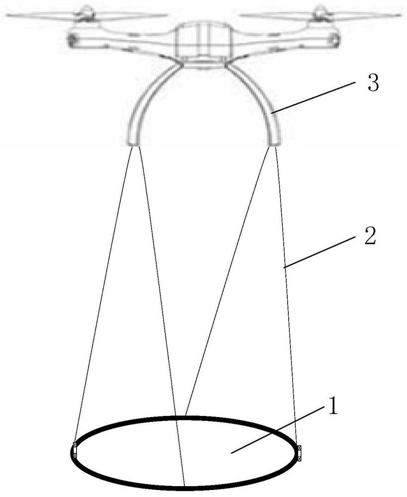
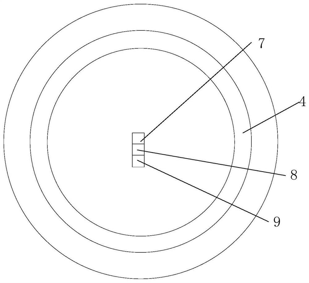
[0054] Such as figure 1 , figure 2 and image 3 Commonly shown, a UAV semi-aviation transient electromagnetic receiving coil flight parameter measurement device, including a receiver 1, an attitude calculation module 7, a nine-axis attitude sensor 8, GPS9, a radar altimeter 6 and a transient electromagnetic receiver, The receiver 1 includes a receiver housing 5 and an annular receiving coil 4 arranged in the receiver hou...


PUM


Abstract

The invention discloses an unmanned aerial vehicle semi-aviation transient electromagnetic receiving coil flight parameter measuring device and method. The device comprises a receiver, an attitude resolving module, a nine-axis attitude sensor, a GPS, a radar altimeter, a transient electromagnetic receiver and flight quality inspection software. The receiver comprises a receiver shell and an annular receiving coil arranged in the receiver shell, the receiving coil is connected with the bottom of the unmanned aerial vehicle through four anti-torsion ropes, and self-rotation of the coil in the flight process can be effectively reduced. The attitude resolving module, the nine-axis attitude sensor and the GPS are all fixedly arranged at the circle center of the receiving coil; the course angleof the receiving coil can be accurately obtained; the attitude of the receiving coil is calculated in real time, a radar altimeter is fixedly arranged below the circle center of the receiving coil, height information for calculating a vertical magnetic component in the data inversion process can be provided, and flight quality inspection software monitors the flight quality by dynamically playingback flight parameters of the receiving coil on site.

Description

technical field [0001] The invention relates to the field of geophysical transient electromagnetic exploration, in particular to a device and method for measuring flight parameters of a semi-aviational transient electromagnetic receiving coil of an unmanned aerial vehicle. Background technique [0002] The receiving subsystem of the UAV semi-aerial transient electromagnetic survey system is mainly composed of the UAV, the receiving coil suspended under the UAV, and the airborne transient electromagnetic receiver. The commonly used ground transient electromagnetic receiving coil is directly hung under the UAV with ropes, and its shell structure and hanging technology are not suitable for the air flight of the receiving subsystem of the semi-aerial transient electromagnetic survey system. During the working process, due to the influence of turbulent airflow and non-uniform speed in the air and the transmission of the vibration of the UAV body, it is difficult for the receiving...

Claims


Application Information

Patent Timeline
Patent Type & Authority Patents(China)
IPC IPC(8): G01V3/10G01R33/04G01C21/16G01C21/18G01C25/00
CPCG01C21/165G01C21/18G01C25/00G01R33/04G01V3/10
Inventor 高嵩钟辉宏王绪本李源何虎鲜鹏飞
Owner CHENGDU UNIVERSITY OF TECHNOLOGY
Learn More