Spray head adjusting mechanism

A technology for adjusting mechanisms and nozzles, which is applied in the direction of manufacturing tools, abrasives, metal processing equipment, etc., and can solve problems such as the inability to change the spray angle, the inability to automatically adjust the spray distance of the nozzle, and the complicated fixed structure.

Active Publication Date: 2019-07-16
GUANGZHOU UNIVERSITY
View PDF10 Cites 2 Cited by
  • Summary
  • Abstract
  • Description
  • Claims
  • Application Information

AI Technical Summary

Problems solved by technology

The central rod of this device is fixed between the base and the threaded connection, and the angle is adjusted by feeling. The fixing structure is more complicated. At the same time, due to the particularity of the injector, this mechanism cannot be well applied in the field of intensive grinding.
[0004] Another example is an invention patent named "sandblasting machine". The sandblasting machine described in this invention includes: a sandblasting tank, a driving device and a nozzle assembly, etc., wherein the sandblasting tank and the nozzle assembly are conn

Method used


Image

  • Spray head adjusting mechanism
  • Spray head adjusting mechanism
  • Spray head adjusting mechanism

Examples


Example Embodiment

[0022] The present invention will be further described in detail below in conjunction with the drawings and specific embodiments.

[0023] In order to facilitate the unified view of the various reference signs in the drawings of the specification, the reference signs appearing in the drawings of the specification are described as follows:

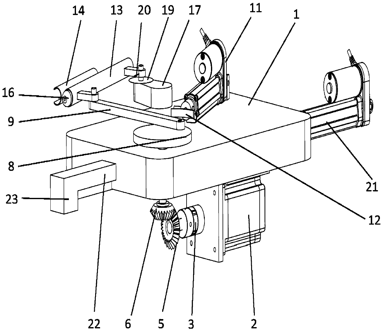
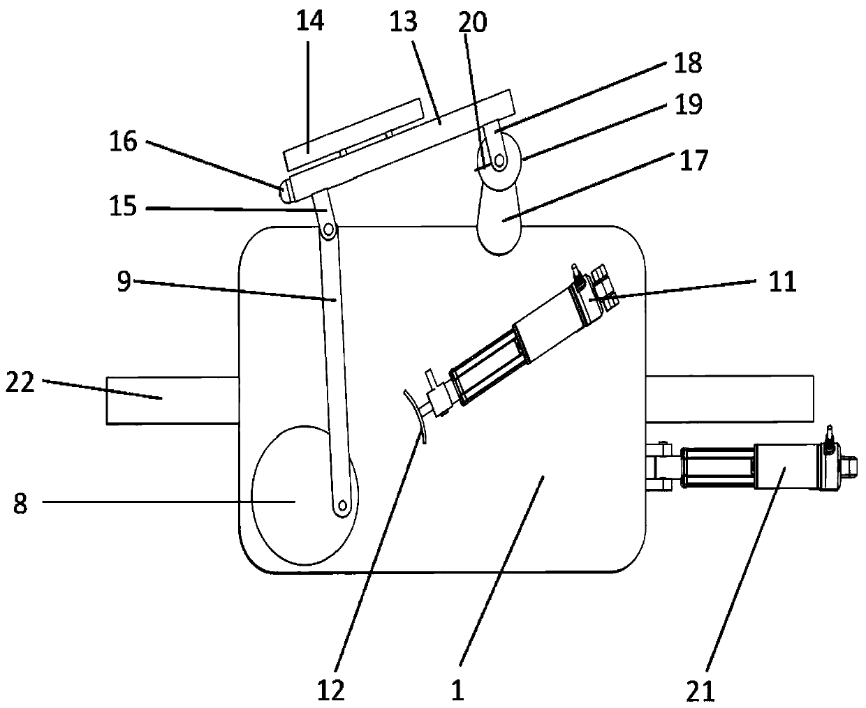
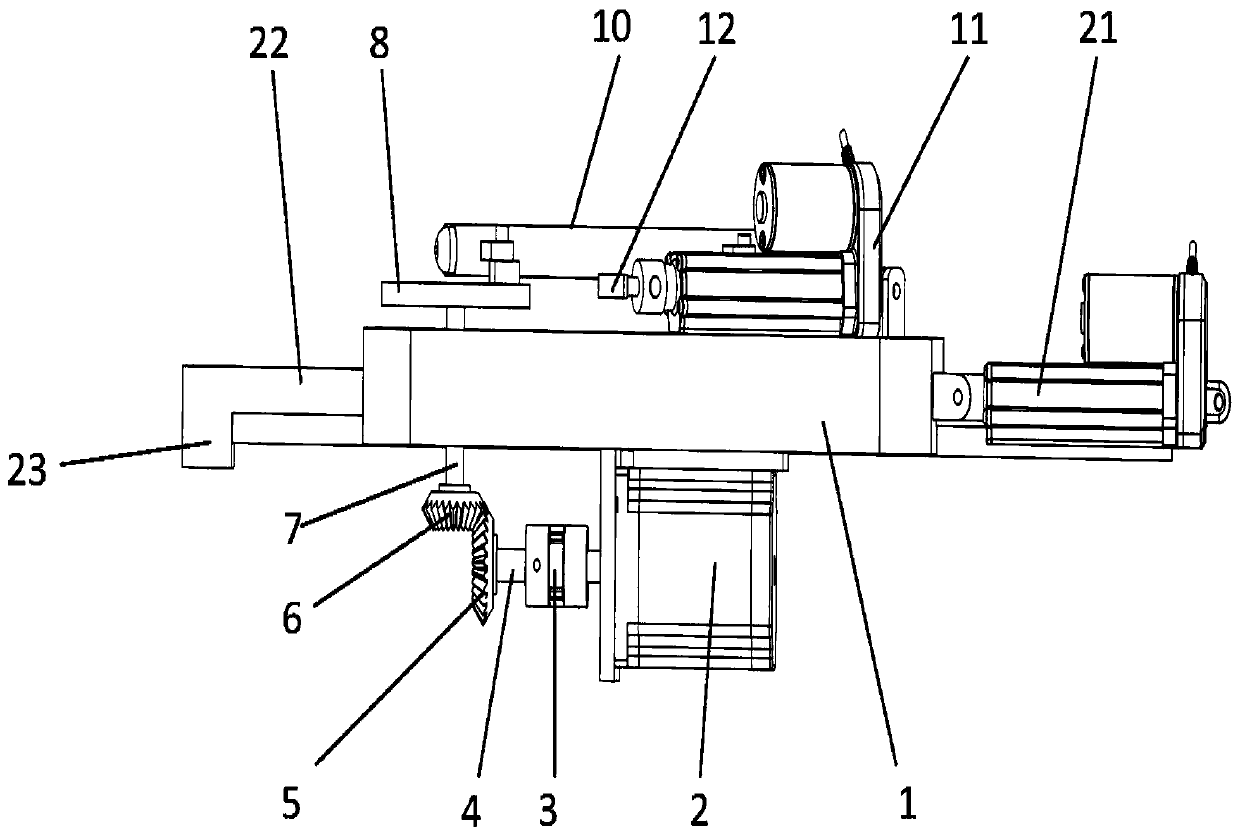
[0024] 1 is the bottom plate, 2 is the motor, 3 is the coupling, 4 is the first straight shaft, 5 is the first bevel gear, 6 is the second bevel gear, 7 is the second straight shaft, 8 is the turntable, and 9 is the connecting rod , 10 is the nozzle assembly, 11 is the first electric push rod, 12 is the friction plate, 13 is the round tube, 14 is the nozzle sleeve, 15 is the first connecting piece, 16 is the laser pointer, 17 is the boss, 18 is the Two connecting pieces, 19 is a dial, 20 is a pointer, 21 is a second electric push rod, 22 is a fixed guide rail, and 23 is a limit block.

[0025] Combine figure 1 , figure 2 , image 3 As shown, a ...


PUM


Abstract

The invention belongs to the technical field of spray head adjusting mechanisms, and relates to a spray head adjusting mechanism which comprises a bottom plate, a motor arranged on the bottom plate, acoupler connected with the output end of the motor, a first straight shaft fixedly connected with the coupler, a first bevel gear fixedly connected with the first straight shaft, a second bevel gearengaged with the first bevel gear, a second straight shaft fixedly connected with the second bevel gear, a turntable fixedly connected with the second straight shaft, a connecting rod hinged to the turntable and a spray head assembly hinged to the bottom plate. The connecting rod for driving the spray head assembly to rotate around the bottom plate is hinged to the spray head assembly. The spray head adjusting mechanism further comprises a first electric push rod and a second electric push rod, the first electric push rod is fixed on the bottom plate, and the output end of the second electricpush rod is hinged to the side surface of the bottom plate. The spray head adjusting mechanism can adjust the spray angle of a spray head and also can adjust the spray distance of the spray head.

Description

technical field [0001] The invention relates to the technical field of nozzle adjustment, in particular to a nozzle adjustment mechanism. Background technique [0002] In recent years, Professor Liu Xiaochu of Guangzhou University has proposed a new method of enhanced grinding processing that integrates surface strengthening and grinding micro-cutting. The abrasive composed of steel balls, grinding powder and grinding liquid is sprayed on the bearing sleeve by high-pressure gas. The surface of the ring can obtain a surface strengthening layer with better mechanical properties; however, the existing equipment is to set the injector in the cage and then fix it through threaded connection. If it is necessary to adjust the spray angle, it can only be adjusted manually. Angle, since it is obviously not accurate enough to adjust the spray angle without reference to human feeling, it is also very inconvenient to adjust the spray angle by constantly turning the screw. [0003] In o...

Claims


Application Information

Patent Timeline
IPC IPC(8): B24C9/00C21D7/06
CPCB24C9/00C21D7/06
Inventor 刘晓初黄建枫萧金瑞黄伟锋朱锐高伟林
Owner GUANGZHOU UNIVERSITY
Why Eureka
Try Eureka