Size-adjustable sucker set

A technology of size and suction cup, applied in the direction of manipulators, chucks, manufacturing tools, etc., can solve the problems of slow production cycle, repeated disassembly and replacement time, and inability to realize common handling structure.

Pending Publication Date: 2019-07-16
华普电子(常熟)有限公司
View PDF0 Cites 2 Cited by
  • Summary
  • Abstract
  • Description
  • Claims
  • Application Information

AI Technical Summary

Problems solved by technology

Suction and transportation is a recyclable process in production, so the suction and transportation structure is usually a general-purpose structure. The existing method is to design and locate the suction method according to the actual single product, and it is impossible to realize the common use of the transportation structure.
In the production process of the workshop, it is necessary to involve and make the corresponding suction and handling structures of various products in advance. On the one hand, the transfer cost of the workshop products is increased, and on the other hand, more time for repeated disassembly and replacement is required, which slows down the production cycle.

Method used


Image

  • Size-adjustable sucker set
  • Size-adjustable sucker set
  • Size-adjustable sucker set

Examples


specific Embodiment example 1

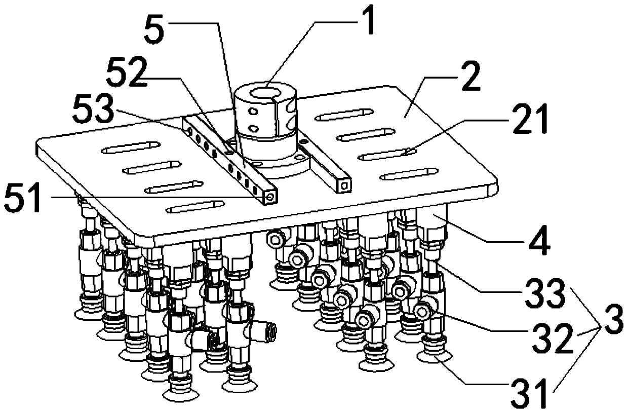
[0029] A size-adjustable suction cup set, comprising: a clamping fixed seat 1 for fixing a mechanical arm, a connecting plate 2, a vacuum suction cup assembly 3, a magnetic adsorption assembly 4, the base of the clamping fixed seat 1 and the connecting plate 2 The board surface is fixed by screws, and the vacuum chuck assembly 3 is fixed on the lower end surface of the connection board 2 through the magnetic adsorption assembly 4 .

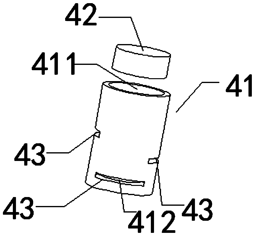
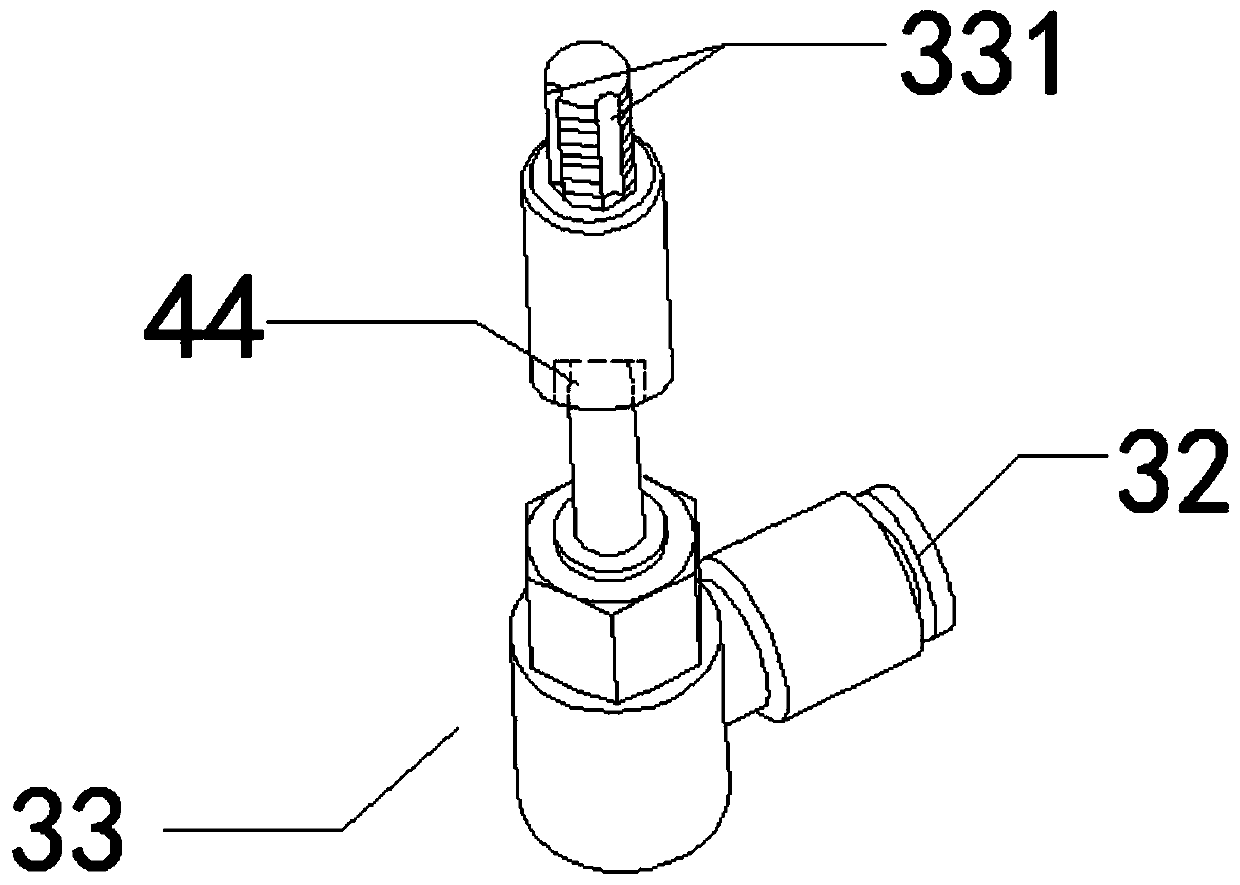
[0030] Wherein, the magnetic adsorption assembly 4 includes a fixed post 41 and a magnetic sheet 42. The upper end of the fixed post 41 is processed with a magnetic sheet accommodating groove 411, and the lower end is processed with a threaded blind hole 412. The magnetic sheet 42 is fixed in the magnetic sheet accommodating groove 411. The vacuum chuck assembly 3 includes a vacuum nozzle 31, an air valve 32, and an air nozzle fixed shaft 33 processed with a central ventilation blind hole, wherein the vacuum suction nozzle 31 is fixed on the lower ...

specific Embodiment example 2

[0035] A size-adjustable suction cup set, comprising: a clamping fixed seat 1 for fixing a mechanical arm, a connecting plate 2, a vacuum suction cup assembly 3, a magnetic adsorption assembly 4, the base of the clamping fixed seat 1 and the connecting plate 2 The board surface is fixed by screws, and the vacuum chuck assembly 3 is fixed on the lower end surface of the connection board 2 through the magnetic adsorption assembly 4 . Wherein, the magnetic adsorption assembly 4 includes a fixed post 41 and a magnetic sheet 42. The upper end of the fixed post 41 is processed with a magnetic sheet accommodating groove 411, and the lower end is processed with a threaded blind hole 412. The magnetic sheet 42 is fixed in the magnetic sheet accommodating groove 411. The vacuum chuck assembly 3 includes a vacuum nozzle 31, an air valve 32, and an air nozzle fixed shaft 33 processed with a central ventilation blind hole, wherein the vacuum suction nozzle 31 is fixed on the lower end of th...

specific Embodiment example 3

[0039] A size-adjustable suction cup set, comprising: a clamping fixed seat 1 for fixing a mechanical arm, a connecting plate 2, a vacuum suction cup assembly 3, a magnetic adsorption assembly 4, the base of the clamping fixed seat 1 and the connecting plate 2 The board surface is fixed by screws, and the vacuum chuck assembly 3 is fixed on the lower end surface of the connection board 2 through the magnetic adsorption assembly 4 . Wherein, the magnetic adsorption assembly 4 includes a fixed post 41 and a magnetic sheet 42. The upper end of the fixed post 41 is processed with a magnetic sheet accommodating groove 411, and the lower end is processed with a threaded blind hole 412. The magnetic sheet 42 is fixed in the magnetic sheet accommodating groove 411. The vacuum chuck assembly 3 includes a vacuum nozzle 31, an air valve 32, and an air nozzle fixed shaft 33 processed with a central ventilation blind hole, wherein the vacuum suction nozzle 31 is fixed on the lower end of th...


PUM


Abstract

A size-adjustable sucker set comprises a clamping type fixing base for fixing a mechanical arm, a connecting plate, a vacuum sucker assembly and a magnetic adsorption assembly. A base of the clampingtype fixing base is fixed to the plate surface of the connecting plate through a screw, the vacuum sucker assembly is fixed to the lower end surface of the connecting plate through the magnetic adsorption assembly. Multiple products with different sizes and shapes are sucked and moved by changing the number and placing positions of vacuum adsorption assemblies. The height mounting position of an air nozzle fixing shaft and a fixing column can be changed through a positioning screw to change the acting height of a vacuum suction nozzle, and the acting angle of the vacuum suction nozzle is changed through a rotating assembly, so that the acting range of the vacuum adsorption assembly 3 is 360 degrees with no dead angle. The size-adjustable sucker set adapts to suction and transfer of products with more sizes and complex shapes, on one hand, the problem that a suction structure is repeatedly removed and installed for different products is avoided, and on the other hand, different suctionstructures do not need to be designed and produced by spending the high cost, the product production cost is reduced, and the product production period is shortened.

Description

technical field [0001] The invention relates to the technical field of suction and transportation of products in the electronics industry, in particular to a size-adjustable suction cup set. Background technique [0002] With the rapid development of the electronics industry, the traditional human sea production mode is gradually replaced by fully automatic production lines. The automatic production line first needs to be designed for handling to replace labor, and the purpose of suction and handling is to achieve material transfer. Suction and transportation is a recyclable process in production, so the suction and transportation structure is usually a general-purpose structure. The existing method is to design and locate the suction method according to the actual single product, and it is impossible to realize the common use of the transportation structure. In the production process of the workshop, it is necessary to involve and make the suction and handling structures co...

Claims


Application Information

Patent Timeline
IPC IPC(8): B25J15/06
CPCB25J15/0633
Inventor 崔宁宁欧阳铁登
Owner 华普电子(常熟)有限公司
Why Eureka
Try Eureka