
Vehicle-mounted airflow generating device

An air flow generation and vehicle technology, which is applied in the direction of the vehicle exterior cleaning device, etc., can solve the problems of difficulty in movement, difficulty in adjusting the position of the air jet outlet on the cleaning equipment, and the inability of the jet outlet to be relatively fast, and achieve the effect of reducing labor costs.

Pending Publication Date: 2019-07-16
重庆军通汽车有限责任公司
View PDF0 Cites 0 Cited by
  • Summary
  • Abstract
  • Description
  • Claims
  • Application Information

AI Technical Summary

Problems solved by technology

[0003] When cleaning the harmful substances adhering to the vehicle, the staff generally move the cleaning equipment of the high-temperature and high-pressure airflow to the vehicle. It is difficult to adjust the position of the air jet outlet, and it is impossible to make the jet outlet and various parts of the vehicle face each other quickly. In severe cases, it will lead to incomplete cleaning of the vehicle and residual harmful substances on the vehicle; and the quality of the cleaning equipment will be greatly shifted. Difficult, when adjusting the position of the cleaning equipment, it consumes a lot of labor costs

Method used


Image

  • Vehicle-mounted airflow generating device
  • Vehicle-mounted airflow generating device
  • Vehicle-mounted airflow generating device

Examples


Embodiment 1

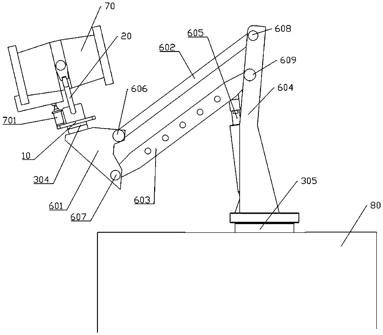
[0033] Embodiment 1 is basically as attached figure 1 Shown: a vehicle-mounted airflow generating device, including an airflow generating mechanism capable of ejecting high-temperature and high-pressure airflow and a support mechanism supporting the airflow generating mechanism, the airflow generating mechanism is an aeroengine 70, and the aeroengine 70 is a turbojet engine, supporting The mechanism includes a first supporting unit on which the airflow generating mechanism is installed, a foldable second supporting unit and a connecting rotating unit connecting the supporting unit and the vehicle 80 .

[0034] Such as figure 1As shown, the connecting rotating unit includes a supporting platform 10, a fixed frame 20, a first rotating unit that drives the supporting platform 10 to rotate, and a second rotating unit that drives the generating mechanism to rotate, and the first rotating unit drives the generating mechanism to rotate 340° or 360° ° of the first hydraulic motor 304...

Embodiment 2

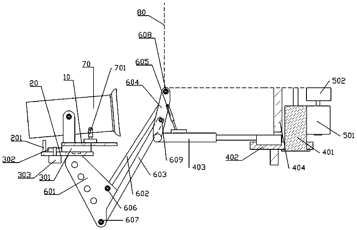
[0044] Embodiment 2 is basically as attached figure 2 , attached image 3 And attached Figure 4 As shown, and the difference between embodiment 2 and embodiment 1 is that the second support unit, the first rotation unit and the second rotation unit are improved.

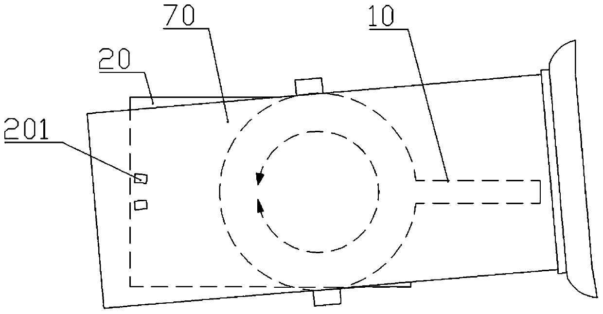
[0045] as attached figure 2 As shown, the first rotating unit includes a first gear 301, a driving wheel 302 and a first motor 303 that can be rotated forward and backward. Surface rotation connection, the first motor 303 is welded on the lower surface of the fixed frame 20, and the rotating shaft of the first motor 303 passes through the fixed frame 20 and is welded with the driving wheel 302, and the driving wheel 302 meshes with the first gear 301; while the fixed frame 20 Two limit blocks 201 that limit the rotation of the support platform 10 to 340° are provided on the left side of the left side.

[0046] Such as Figure 4 As shown, the second rotating unit includes a second gear 401, a connection platfo...


PUM


Abstract

The invention relates to the field of mechanical equipment accessories, and particularly discloses a vehicle-mounted airflow generating device. The vehicle-mounted airflow generating device comprisesan airflow generating mechanism capable of ejecting high-temperature and high-pressure airflow and a supporting mechanism for supporting the airflow generating mechanism, and the supporting mechanismis detachably connected with a vehicle. The vehicle-mounted airflow generating device can eject the high-temperature and high-pressure airflow to the surface of the vehicle to remove harmful substances adhered on the vehicle.

Description

technical field [0001] The invention belongs to the field of mechanical equipment accessories, and in particular relates to a vehicle-mounted airflow generating device. Background technique [0002] Vehicles are often used in army drills. After the drill, poisonous agents, biological warfare agents, radioactive substances, dust and other harmful substances are easy to adhere to the vehicles. Therefore, after the vehicles are used, they generally need to be cleaned. When removing harmful substances adhering to the vehicle, it is generally removed by high-temperature and high-pressure airflow flushing. When it comes to high-temperature, high-pressure airflow flushing of vehicles, it is necessary to use high-quality cleaning equipment. [0003] When cleaning the harmful substances adhered to the vehicle, the staff generally move the cleaning equipment of the high-temperature and high-pressure airflow to the vehicle, and the outlet of the airflow is opposite to each surface of t...

Claims


Application Information

Patent Timeline
Patent Type & Authority Applications(China)
IPC IPC(8): B60S3/04
CPCB60S3/04
Inventor 马宝玉李经涛谢邱黎刘显杰张韵伍思强邱嘉刘志明
Owner 重庆军通汽车有限责任公司
Learn More