Rail-mounted distance measuring device capable of being prevented from falling from rail

A distance-measuring device and anti-dropping technology, which is applied in the direction of measuring devices, mechanical measuring devices, and mechanical devices, etc., can solve problems such as easy to walk in S-curves, the ratio of data to actual distance exceeds the limit, and the device is difficult to pass, etc., to achieve smooth walking Effect

Pending Publication Date: 2019-07-16
THE 1ST ENG CO LTD OF CHINA RAILWAY CONSTR ELECTRIFICATION BUREAU GRP
View PDF1 Cites 0 Cited by
  • Summary
  • Abstract
  • Description
  • Claims
  • Application Information

AI Technical Summary

Problems solved by technology

[0003] The traditional measurement mode mostly uses a tape measure or a track rangefinder to measure. In the tape measure mode, due to the different accuracy and material of the tape produced by different manufacturers, the degree of expansion is different. During the measurement process, the force of pulling the ruler will be different The measurement results have a big impact, and the ruler will become longer after multiple pulls, and the reading will be inaccurate
Secondly, there are too many human factors involved. The common tape measure commonly used for measurement is mostly 50 meters or 100 meters. There will be human errors in each ruler’s rise and fall and reading. The interval ranges from 600-1000 meters for each track section, and multiple cycles of footage are required. It can only be completed, the ratio of the data obtained after the accumulation of multiple errors to the actual distance is very likely to exce

Method used


Image

  • Rail-mounted distance measuring device capable of being prevented from falling from rail
  • Rail-mounted distance measuring device capable of being prevented from falling from rail
  • Rail-mounted distance measuring device capable of being prevented from falling from rail

Examples


Embodiment 1

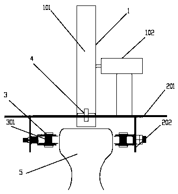
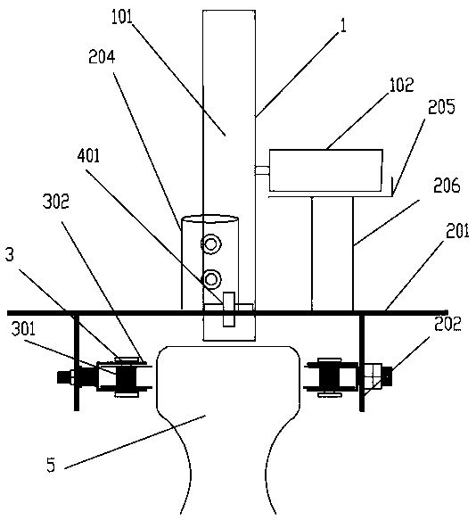
[0026] An anti-fall track distance measuring device, such as figure 1 As shown, it includes an anti-fall mechanism and a distance measuring instrument 1 for walking counting. The distance measuring instrument 1 includes a distance measuring wheel 101 that walks on the upper surface of the rail 5 to measure the length of the rail and is used to calculate the rolling distance of the distance measuring wheel 101. The distance counter 102, the distance measuring wheel 101 is connected with the counter 102 through the central axis through the steel pipe. When measuring, the distance measuring wheel 101 rolls close to the upper surface of the rail 5, and at the same time, the counter 102 calculates the distance of the distance measuring instrument 101. The rolling distance is displayed on the instrument panel thereon, and the counter 102 is provided with a reset switch, which is convenient for the reading of the counter 102 to be reset to zero before each measurement.

[0027] The a...

Embodiment approach

[0030] 1. Use a tape measure to measure 100 meters of rail 5, and mark both ends, one end as "0" and the other end as "100".

[0031] 2. Put the distance measuring device of the present invention on the rail 5, coincide the contact point between the distance measuring wheel 101 and the rail 5 with the "0" point, push the device forward at a constant speed to the place marked "100", and the distance measuring wheel The contact point of 101 and rail 5 coincides with the line of "100" mark, and the reading on the calibration rangefinder is 100 meters.

[0032] 3. Put the distance measuring device of the present invention at the starting point of the section to be measured on the rail 5, pull the reset switch, make the reading of the counter 102 be zero, push the device at a constant speed, rely on its own gravity and the function of the anti-fall mechanism Limiting and guiding functions, the device can move forward smoothly along the rail 5, push it to the end of the measured sec...

Embodiment 2

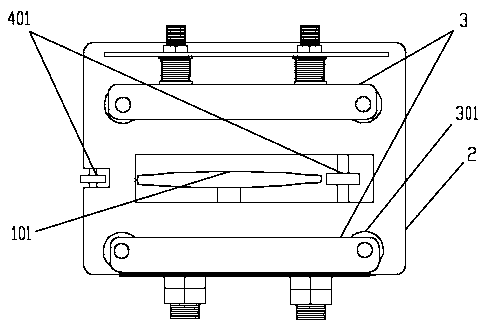
[0035] This embodiment is an improvement on the basis of Embodiment 1, as image 3 , 4As shown in and 5, the limit pulley 301 goes deep into the groove of a U-shaped limit plate 302, and is connected with the U-shaped limit plate 302 through the central axis by the pin shaft, and the edge of the limit pulley 301 starts from the U-shaped limit plate. The bit plate 302 leaks out near the side of the rail 5 and rolls against the side of the rail 5 . One side of the U-shaped limiting plate 302 close to the vertical fixing plate 202 is connected to the vertical fixing plate 202 through bolts 303 . The vertical fixing plate 202 is provided with a plurality of vertical slots 2021 for connecting the limiting component 3 with the vertical fixing plate 202 through the slots 2021 with bolts 303 , thereby realizing the height adjustment of the limiting component 3 . The bolt 303 can be fixed at any height in the slot 2021, thereby realizing the adjustment of the height of the limiting a...


PUM


Abstract

The invention relates to a rail-mounted distance measuring device capable of being prevented from falling from a rail. The rail-mounted distance measuring device comprises a distance measuring instrument and a mechanism preventing falling from the rail; the distance measuring instrument comprises a distance measuring wheel and a counting instrument; the mechanism preventing falling from the rail comprises a rail-mounted support and guiding assemblies; the rail-mounted support comprises a horizontal fixing plate and a vertical fixing plate, wherein the inner side of the vertical fixing plate isprovided with a limiting assembly; the limiting assembly comprises a plurality of limiting pulleys, the limiting pulleys are tightly attached to the side face of the steel rail to control the distance measuring wheel to travel in the traveling direction of the steel rail, the limiting pulleys do not make contact with a rail web, and thus the distance measuring wheel can pass through a bifurcatedarea smoothly; the guiding assemblies are arranged on the front part and the rear part of the distance measuring wheel to assist the distance measuring wheel in traveling more smoothly on the steel rail; and the limiting assembly can be adjustably fixed on the vertical fixing plate through bolts, the height of the limiting assembly can be adjusted according to actual needs, meanwhile the transverse length of the limiting assembly can be changed by adjusting the bolts and nuts, and then the limiting assembly adapts to steel rails of different specifications. The length of the steel rails can beaccurately measured in railway engineering, and the situation that during measuring, the distance measuring wheel slides, and then the rail-mounted distance measuring device deviates from the steel rail traveling direction is prevented.

Description

technical field [0001] The invention relates to the technical field of railway engineering measurement, in particular to a track distance measuring device for preventing falling off. Background technique [0002] Railway engineering surveying is the surveying work for the survey, design, construction and operation management of railway engineering. Railway engineering measurement is one of the most basic and critical links in railway engineering, so it is particularly important. [0003] The traditional measurement mode mostly uses a tape measure or a track rangefinder to measure. In the tape measure mode, due to the different accuracy and material of the tape produced by different manufacturers, the degree of expansion is different. During the measurement process, the force of pulling the ruler will be different There is no small effect on the measurement results, and after multiple pulls the ruler will become longer and the reading will be inaccurate. Secondly, there are...

Claims


Application Information

Patent Timeline
IPC IPC(8): G01B5/02B61K9/08
CPCB61K9/08G01B5/0002G01B5/0009G01B5/02
Inventor 康小平薛翠翠
Owner THE 1ST ENG CO LTD OF CHINA RAILWAY CONSTR ELECTRIFICATION BUREAU GRP
Why Eureka
Try Eureka