
Revolving support mechanism applied to shot blasting for inner wall of steel tube

A shot blasting cleaning and slewing support technology, which is applied to used abrasive treatment devices, abrasive jet machine tools, abrasives, etc., can solve the problems of inability to effectively ensure lubrication and sealing effect, inconvenient processing and assembly, and poor sealing performance. Achieve outstanding substantive features, compact structure, good sealing and lubrication performance

Inactive Publication Date: 2017-01-25
SHANDONG KAITAI SHOT BLASTING MACHINERY
View PDF8 Cites 0 Cited by
  • Summary
  • Abstract
  • Description
  • Claims
  • Application Information

AI Technical Summary

Problems solved by technology

Among them, the inner ring of the bearing is connected with the transmission bracket, and the roller and the roller bracket are arranged on the peripheral surface of the outer ring of the bearing, but this structure has the following defects: 1. The roller bracket needs to be installed on the outer ring of the bearing, and the The ring is connected with the transmission bracket and the shot blasting machine, which is inconvenient for processing and assembly, and inconvenient for disassembly; 2. During the rotation of the steel pipe, the bearing wears seriously and is prone to failure. After damage, it is inconvenient to repair. It is necessary to directly replace the entire rotation mechanism, and the maintenance cost is high; 3. Since the rolling in the circumferential direction is realized through the bearing, lubrication and sealing are particularly important, but the sealing performance in the above invention is poor, and the lubrication and sealing effect cannot be effectively guaranteed

Method used


Image

  • Revolving support mechanism applied to shot blasting for inner wall of steel tube
  • Revolving support mechanism applied to shot blasting for inner wall of steel tube
  • Revolving support mechanism applied to shot blasting for inner wall of steel tube

Examples


specific Embodiment approach

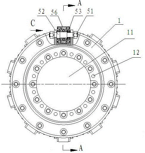
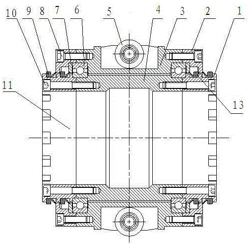
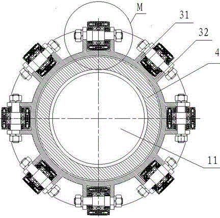
[0027] Specific implementation methods: such as Figure 1~Figure 6 As shown, the present invention provides a rotary support mechanism applied to shot blasting on the inner wall of steel pipes, including rolling parts in the circumferential direction and rolling parts in the axial direction, wherein the rolling parts in the circumferential direction include supporting inner rings 4, inner retaining rings 1, The supporting outer ring 3, the outer retaining ring 2 and the rolling bearing 6, the inner retaining ring 1 are respectively installed on the left and right sides of the supporting inner ring 4, and are fixedly connected by hexagon socket bolts 10; the outer retaining ring 2 is respectively installed on the supporting outer ring 3 The left and right sides are fixedly connected by hexagon socket bolts 8. One end of the rolling bearing 6 away from the supporting inner ring 4 is provided with a bearing retaining ring 7 , one end face of the bearing retaining ring 7 is in con...


PUM


Abstract

The invention provides a revolving support mechanism applied to shot blasting for an inner wall of a steel tube. The revolving support mechanism comprises a circumferential rolling component and at least one axial rolling unit, wherein the axial rolling units are arranged on the outer peripheral face of the circumferential rolling component at intervals; the circumferential rolling component comprises a support inner ring, a rolling bearing and a support outer ring; an inner ring of the rolling bearing is connected with the support inner ring in a matching way; an outer ring of the rolling bearing is connected with the support output ring in a matching way; the axial rolling units are detachably connected with the support outer ring. By adopting the revolving support mechanism, the axial rolling units can be mounted conveniently, a transmission frame can be connected conveniently with an impeller head, and convenience is brought to assembly; moreover, the revolving support mechanism is stressed uniformly, walks smoothly, is low in fault rate, and is convenient to disassemble and repair after a fault; moreover, the revolving support mechanism is reasonable in design and has good sealing and lubricating effects, and smooth running of shot blasting can be ensured effectively.

Description

technical field [0001] The invention relates to a rotary support mechanism, in particular to a rotary support mechanism applied to the shot blasting cleaning of the inner wall of a steel pipe. Background technique [0002] In order to remove the rust and oxide layer on the surface of the steel pipe and reduce the pollution caused by the steel pipe itself to the conveying medium, it is necessary to carry out anti-rust and rust-removing treatment on the surface. Shot blasting treatment can obtain uniform completion due to its high working efficiency, stable quality The surface is widely used. During the shot blasting process, the shot blaster moves in a straight line while the steel pipe is rotating to realize the cleaning of the inner wall of the steel pipe. Since the length of the steel shot transmission bracket is longer than that of the steel pipe, it is necessary to support the front end of the steel shot transmission bracket on the inner wall of the steel pipe, that is,...

Claims


Application Information

Patent Timeline
IPC IPC(8): B24C3/32B24C9/00
CPCB24C3/325B24C9/00
Inventor 张朝阳李德发李长春吴成民王瑞国王守仁徐银莲高建勇
Owner SHANDONG KAITAI SHOT BLASTING MACHINERY
Learn More