
Walking stepless speed change adjusting mechanism for lawn mower

A technology of stepless speed change and adjustment mechanism, which is applied in the direction of mechanical equipment, control devices, belts/chains/gears, etc. It can solve the problems of short service life of the belt, heavy backing, and large space occupation, and achieves a practical and firm structure and avoids walking Weak, simple structure effect

Active Publication Date: 2013-12-25
宁波新合博园林机械有限公司
View PDF4 Cites 1 Cited by
  • Summary
  • Abstract
  • Description
  • Claims
  • Application Information

AI Technical Summary

Problems solved by technology

The traditional lawn mower speed change mechanism is an external clutch mechanism with a tension pulley in the middle of the driving pulley and the driven pulley. This clutch mechanism has many disadvantages during use: it needs to add a tension pulley mechanism, takes up a lot of space, and the V-belt is not Suitable for reverse twists and turns, short belt life
Lawn mowers with clutch and continuously variable speed integrated control mechanism at the same time, such as the lawn mower clutch and continuously variable speed integrated control mechanism of the Chinese patent document announcement 200910207840.4, a zipper to simultaneously control the lawn mower self-propelled clutch And the continuously variable transmission, the speed change is completed by tensioning the belt clutch from the pulley on the self-propelled device, there will be technical problems such as heavy back, the speed change will fail after the belt is stretched, the speed change is not obvious, and the speed change range is small.

Method used


Image

  • Walking stepless speed change adjusting mechanism for lawn mower
  • Walking stepless speed change adjusting mechanism for lawn mower
  • Walking stepless speed change adjusting mechanism for lawn mower

Examples


Embodiment Construction

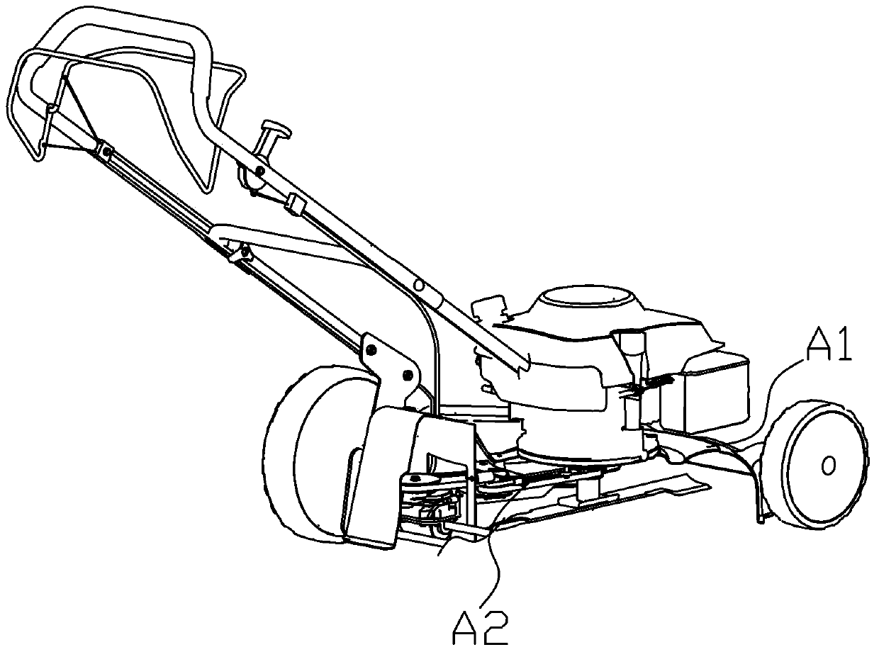
[0024] Such as figure 1 , 2 , 3, 4, 5, and 6. What the present invention discloses is a walking stepless speed change adjustment mechanism of a lawn machine. The present invention is to change the speed of the lawn machine. The specific technical scheme is as follows:

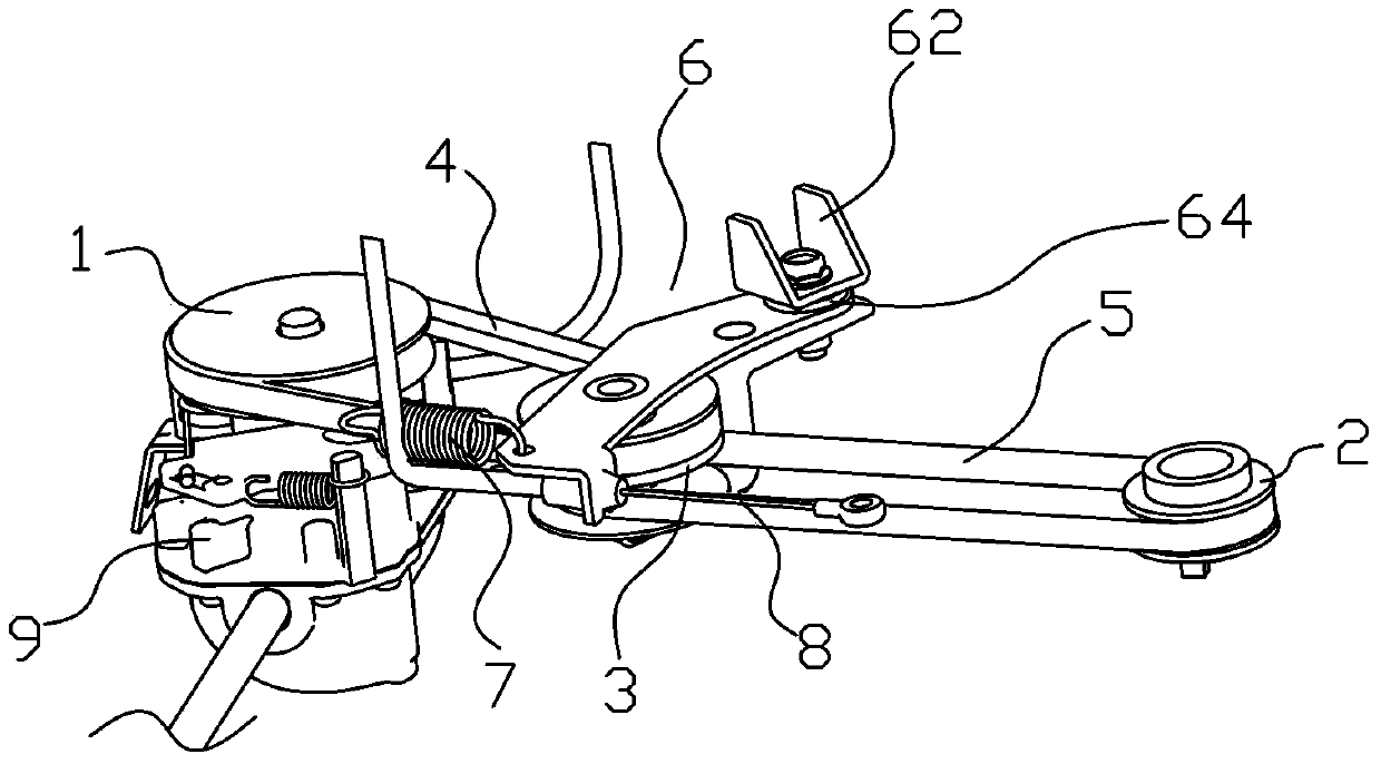
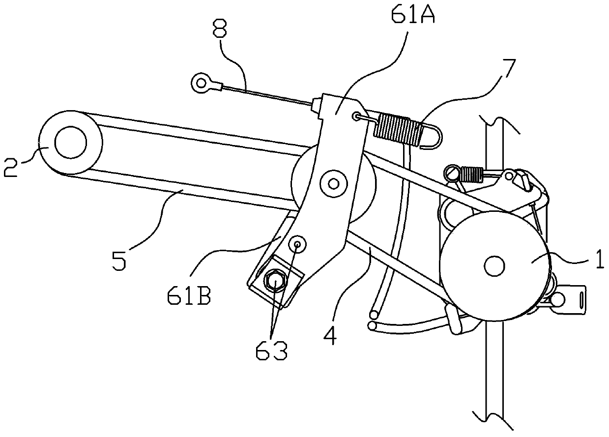
[0025] This continuously variable speed adjustment mechanism is installed in the interior of the lawn machine body A1, which includes a slave pulley 1, a main pulley 2, a variable speed pulley set 3, a first variable speed trimming belt 5 and a second variable speed trimming belt 4, so The speed change pulley set 3 includes an upper speed change pulley 31A, a lower speed change pulley 31B and a speed change main shaft 32 connecting the upper speed change pulley 31A and the lower speed change pulley 31B, located between the upper speed change pulley 31A and the lower speed change pulley 31B A speed change wheel 33 is movably installed, and the speed change wheel 33 can move up and down along the speed change ma...


PUM


Abstract

The invention belongs to the field of lawn mower mechanical equipment and particularly relates to a walking stepless speed change adjusting mechanism for a lawn mower. The stepless speed change adjusting mechanism is installed in a lawn mower body and comprises a driven belt pulley, a driving belt pulley, a speed change belt pulley set, a first speed change edge cutting belt and a second speed change edge cutting belt. The speed change belt pulley set comprises an upper speed change belt pulley, a lower speed change belt pulley and a speed change spindle connected with the upper speed change belt pulley and the lower speed change belt pulley, a change wheel is movably installed between the upper speed change belt pulley and the lower speed change belt pulley and can move up and down along the speed change spindle, the driven belt pulley is movably connected to the speed change belt pulley set through the second speed change edge cutting belt, and the driving belt pulley is movably connected to the speed change belt pulley set through the first speed change edge cutting belt. The walking speed of the lawn mower is changed through the walking stepless speed change adjusting mechanism, and the walking stepless speed change adjusting mechanism has the advantages of working stably and being simple in processing process and long in service life and the like.

Description

technical field [0001] The invention belongs to the field of lawn mower mechanical equipment, and in particular relates to a walking stepless speed-variable adjustment mechanism of the lawn mower. Background technique [0002] The speed change mechanism of the lawn machine is a mechanism for changing the forward speed of the lawn machine to meet the owner's requirement for mowing speed. The speed change mechanism of the lawn machine is located on the chassis of the lawn machine. The traditional lawn machine speed change mechanism is an external clutch mechanism with a tension pulley in the middle of the driving pulley and the driven pulley. This clutch mechanism has many disadvantages during use: it needs to add a tension pulley mechanism, takes up a lot of space, and the V-belt is not It is suitable for reverse twists and turns, and the belt has a short service life. Lawn mowers with clutch and continuously variable speed integrated control mechanism at the same time, suc...

Claims


Application Information

Patent Timeline
Patent Type & Authority Applications(China)
IPC IPC(8): B60K17/06F16H9/04
Inventor 但成兵邓华明肖志平李吉武
Owner 宁波新合博园林机械有限公司
Learn More