
Optical lens for virtual reality helmet

An optical lens and virtual reality technology, applied in the field of optical systems, can solve the problems of inability to meet the needs of users' immersion and experience, small field of view, and insufficient image quality, and achieve light weight and large field of view. , the effect of small distortion

Pending Publication Date: 2019-07-16
SUZHOU UNIV OF SCI & TECH
View PDF0 Cites 3 Cited by
  • Summary
  • Abstract
  • Description
  • Claims
  • Application Information

AI Technical Summary

Problems solved by technology

[0003] At present, most virtual reality display systems adopt a single-chip or two-chip structure. The single-chip structure has the disadvantages of a small field of view and unimaginable image quality. The single-chip structure and two-chip structure cannot meet the needs of users The need for immersion and experience in virtual reality

Method used


Image

  • Optical lens for virtual reality helmet
  • Optical lens for virtual reality helmet
  • Optical lens for virtual reality helmet

Examples


Embodiment 1

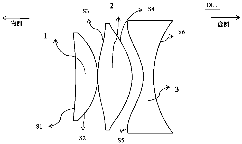
[0031] See attached figure 1 , which is a schematic structural diagram of the optical lens (referred to as OL1) provided in this embodiment. In order to show the features of this embodiment, only structures related to this embodiment are shown, and other structures are omitted. The optical system provided in this embodiment can be a wide-angle eyepiece with a wide-angle level greater than 80 degrees, which can be applied to a virtual reality helmet display system. It can be applied to the virtual reality head-mounted display system with the display screen of Iphone 6Plus. This embodiment is a fixed focus optical system.

[0032] Such as figure 1 As shown, the optical lens OL1 of this embodiment mainly includes in sequence from the object side to the image side: a first lens 1 with positive diopter, a second lens 2 with positive diopter, and a third lens 3 with positive diopter .

[0033] In this embodiment, the display screen is placed on the image side of the optical len...

Embodiment 2

[0049] See attached Figure 6 , which is a schematic structural diagram of the optical lens (referred to as OL2) provided in this embodiment. In order to show the features of this embodiment, only structures related to this embodiment are shown, and other structures are omitted. The optical lens provided in this embodiment can be a wide-angle eyepiece with a wide-angle level greater than 80 degrees, which can be applied to a virtual reality helmet display system, and is suitable for a virtual reality helmet display system with a Samsung Galaxy Note9 display screen. This embodiment provides a fixed-focus optical system. From the object side to the image side, the optical lens OL2 mainly includes: a first lens 1 with positive diopter, a second lens 2 with positive diopter, and a third lens 3 with positive diopter. In this embodiment, the display screen is placed on the image side of the optical lens, the human eye is located on the object side of the optical lens, the distance...


PUM


Abstract

The invention discloses an optical lens for a virtual reality helmet. The optical lens is of a three-piece-type lens set structure and sequentially comprises a first lens, a second lens and a third lens from the object side to the image side along the optical axis, wherein the first lens and the second lens are used for correcting the on-axis aberration and the off-axis aberration, the third lensis used for correcting distortion and dispersion, and the optical lens and a display screen are sequentially placed in front of human eyes. The lens is made of an injection molding material, the weight of the helmet is decreased, and the cost of the helmet is lowered. The amplification factor of an optical system is 5-7 times, the full field angle is 80 degrees, and the maximum distortion is lessthan 11%. The small amplification factor meets the low-resolution screen, and a user can obtain the good immersion sense by using a common mobile phone.

Description

technical field [0001] The invention relates to an optical system, in particular to an optical lens for virtual reality. Background technique [0002] Virtual Reality (Virtual Reality, VR) technology is a computer-generated, interactive, and immersive visual virtual environment proposed in the 1980s. It can generate a variety of virtual environments according to needs, and is widely used in urban planning. , driving training, interior design and other fields. In recent years, with the continuous improvement of computer computing power and the development of sensor technology, various types of virtual reality helmets have appeared on the market, which are basically composed of a display screen or a mobile phone and a pair of eyepieces, through which the human eye can see the display screen On the enlarged image, the sensor senses the changes of the human head and adjusts the images in the left and right display screens, so that the human eyes can see three-dimensional and in...

Claims


Application Information

Patent Timeline
Patent Type & Authority Applications(China)
IPC IPC(8): G02B13/00G02B13/06G02B13/18
CPCG02B13/0035G02B13/06G02B13/18
Inventor 徐越范君柳陈宝华吴泉英
Owner SUZHOU UNIV OF SCI & TECH
Learn More