An optical lens system and a head-mounted display device

An optical lens and lens technology, applied in optics, optical components, magnifiers, etc., can solve the problems of increased design difficulty, insufficient exit pupil diameter, small exit pupil diameter, etc., to improve user experience, excellent imaging quality, and exit pupil. large diameter effect

Active Publication Date: 2018-03-02
青岛宇科软件有限公司
View PDF11 Cites 0 Cited by
  • Summary
  • Abstract
  • Description
  • Claims
  • Application Information

AI Technical Summary

Problems solved by technology

[0003] Public patent: CN104570323A proposes a head-mounted eyepiece system and a head-mounted display device. It is an eyepiece system with 4 lenses. In order to meet the increasing demands of the audience; research on the optical design method of the 3D virtual head-mounted display based on ZEMAX, Infrared and Laser Engineering, 2008,37:279-282 proposes an optical system for the helmet display, which is composed of six lenses , although it has good imaging quality, but its total system length is too long, the exit pupil diameter is not large enough, and the effective exit pupil distance is relatively short; the eyepiece proposed by CN101609208A is also composed of six lenses, although it has relatively high Good image quality, but the diameter of the exit pupil is small, the exit pupil distance is short, which reduces the comfort of the user, and the processing is difficult, and the substrate is thick
[0004] In addition, for the eyepiece system, when the object size is fixed, the smaller the focal length, the larger the field of view, the larger the magnification of the system, and the greater the design difficulty
Although there are many head-mounted systems on the market, the field of view, exit pupil diameter, and exit pupil distance of most products are small, which reduces user comfort

Method used


Image

  • An optical lens system and a head-mounted display device
  • An optical lens system and a head-mounted display device
  • An optical lens system and a head-mounted display device

Examples


Embodiment 1

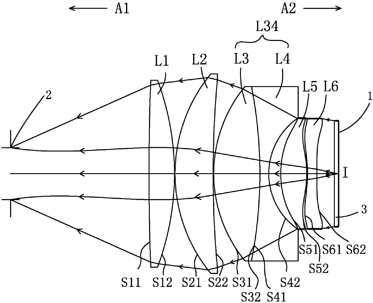
[0092] Such as figure 1 As shown, the optical lens system of the present embodiment includes sequentially along an optical axis I from the light exit side A1 to the light entrance side A2: a diaphragm 2, a first lens L1, a second lens L2, and a third lens L3, a fourth lens L4, a fifth lens L5 and a sixth lens L6, each lens has a refractive power, and has a first surface facing the light-emitting side A1 and allowing light to pass through, and a first surface facing the light-incident side A2 and the second surface that lets light pass through.

[0093] The aperture (aperture stop) 2 is an equivalent aperture, and the entity of this part may not be provided in practical applications. The aperture stop 2 is arranged on the optical axis I of the first lens L1 facing the light-emitting side A1, and is located at The position of the exit pupil of the optical lens system. The protective glass 3 is arranged on the optical axis I of the sixth lens L6 towards the light-incident side ...

Embodiment 2

[0113] Such as Figure 5 As shown, each lens structure of this embodiment is basically the same as that of Embodiment 1, except that the second surface S22 of the second lens L2 of this embodiment is a convex surface, and the second surface S62 of the sixth lens L6 is a convex surface. In addition, the optical parameters and aspheric coefficients of each lens of this embodiment are slightly different from those of Embodiment 1, and the optical parameters and aspheric coefficients of each lens of this embodiment are shown in Table 3 and Table 4 respectively

[0114] Table three, each lens optical parameter data of the second embodiment

[0115]

[0116]

[0117] Table four, the aspherical parameters of the second embodiment

[0118] noodle

K

a2

a4

a6

a8

a10

S51

-24.4

3.20E-04

-2.00E-08

-2.10E-08

S52

-4.1

4.00E-04

6.80E-07

-1.90E-08

S61

2.3

4.50E-04

2.30E-06

-1.30E-08

...

Embodiment 3

[0124] Such as Figure 9 As shown, each lens structure of this embodiment is basically the same as that of Embodiment 1, except that the second surface S22 of the second lens L2 of this embodiment is a convex surface, and the second surface S62 of the sixth lens L6 is a convex surface. In addition, the optical parameters and aspheric coefficients of each lens of this embodiment are slightly different from those of Embodiment 1, and the optical parameters and aspheric coefficients of each lens of this embodiment are shown in Table 5 and Table 6 respectively

[0125] Table five, each lens optical parameter data of the third embodiment

[0126]

[0127] Table six, aspherical parameters of the third embodiment

[0128] noodle

K

a2

a4

a6

a8

a10

S51

-20.1

3.40E-04

2.40E-06

-3.30E-08

S52

-0.5

7.20E-04

1.80E-06

-3.20E-08

S61

1.3

3.60E-04

4.50E-06

-1.40E-08

-6.50E-12

S62

...


PUM


Abstract

The invention relates to a head-mounted display device and its optical lens system. The invention discloses an optical lens system, which sequentially includes a first lens, a second lens, a third lens, a fourth lens, a fifth lens and a sixth lens along the optical axis from the light exit side to the light entrance side, each lens Both have refractive power, the first lens is a positive power lens, the second lens is a positive power lens, the third lens is a positive power lens, the fourth lens is a negative power lens, and the fifth lens is a positive power lens. The lens is a positive power lens and the sixth lens is a negative power lens. The invention also discloses a head-mounted display device with the above-mentioned optical lens system. The invention has the advantages of light weight, compact structure, large field of view, exit pupil diameter and exit pupil distance, improved user experience, excellent imaging quality, high resolution and low cost.

Description

technical field [0001] The present invention relates to a head-mounted display device and its optical lens system, and in particular to a head-mounted display device using a six-piece lens and its optical lens system. Background technique [0002] In recent years, due to the rise of wearable electronic devices, miniaturized display modules including optical lens systems and microdisplays have flourished, and are widely used in head-mounted display devices. Head-mounted display devices are widely used in military, aerospace, medical, entertainment, simulation training and other fields. As head-mounted display devices are more and more widely used, the image quality and comfort of use (the larger the field of view, exit pupil diameter and exit pupil distance, the smaller the volume and the lighter the weight, the comfort of use The higher the requirements are, the higher the imaging quality and the comfort of use mainly depend on the design of the optical eyepiece system. ...

Claims


Application Information

Patent Timeline
Patent Type & Authority Patents(China)
IPC IPC(8): G02B25/00G02B27/01
CPCG02B1/00G02B1/041G02B13/0045G02B25/001G02B27/0101G02B27/017G02B27/0172
Inventor 田玉华张琳孙昊
Owner 青岛宇科软件有限公司
Why Eureka
Try Eureka