Threading machine

A threading machine and body technology, applied in the field of threading machines, can solve the problems of transmission stability, poor coordination, poor synchronization of traction wheels, and many follow-up problems, and achieve the effects of ensuring traction stability, improving stability and long service life.

Pending Publication Date: 2019-07-16
永康市闳骏机电有限公司
View PDF1 Cites 2 Cited by
  • Summary
  • Abstract
  • Description
  • Claims
  • Application Information

AI Technical Summary

Problems solved by technology

[0003] 1. It is necessary to drive the opposite left traction pulley and right traction pulley at the same time. During the threading and lead-in process, the left traction pulley and the right traction pulley need to rotate synchronously. However, this patented product is affected by its transmission structure and cannot ensure long-term traction. The synchronization of the pulleys leads to poor stability and is prone to jamming, that is, due to the low precision of the transmission of the worm gear itself, the synchronization of each traction wheel is poor; while the worm wheel driven by the worm is connected coaxially with each traction wheel, due to the worm gear The transmission generates a lot of heat. With the passage of time and the increase of the frequency of use, the wear of the worm gear is gradually serious until the transmission structure is damaged.
[0004] 2. Since the worm gear can self-lock in reverse, when the cable is transported in place or the worker

Method used


Image

  • Threading machine
  • Threading machine
  • Threading machine

Examples


Embodiment 1

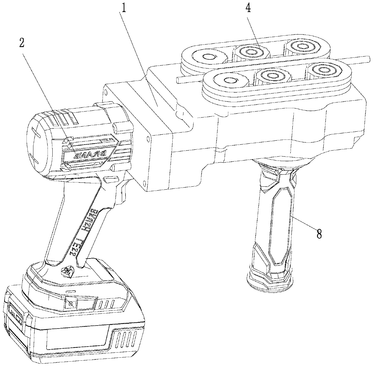
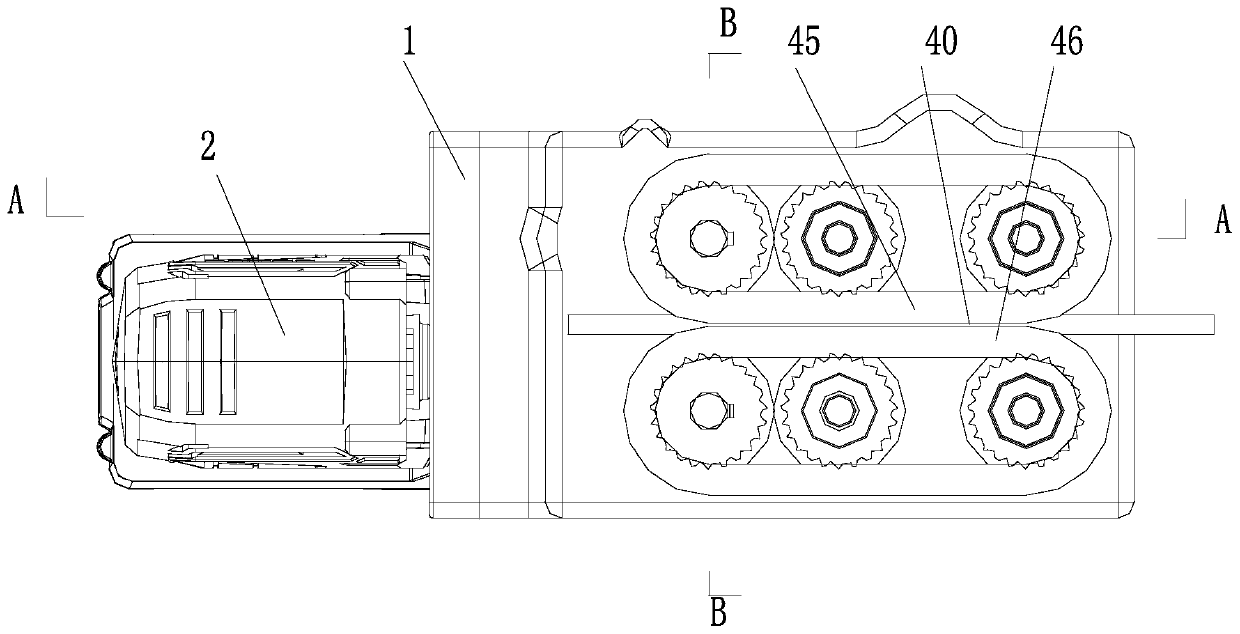
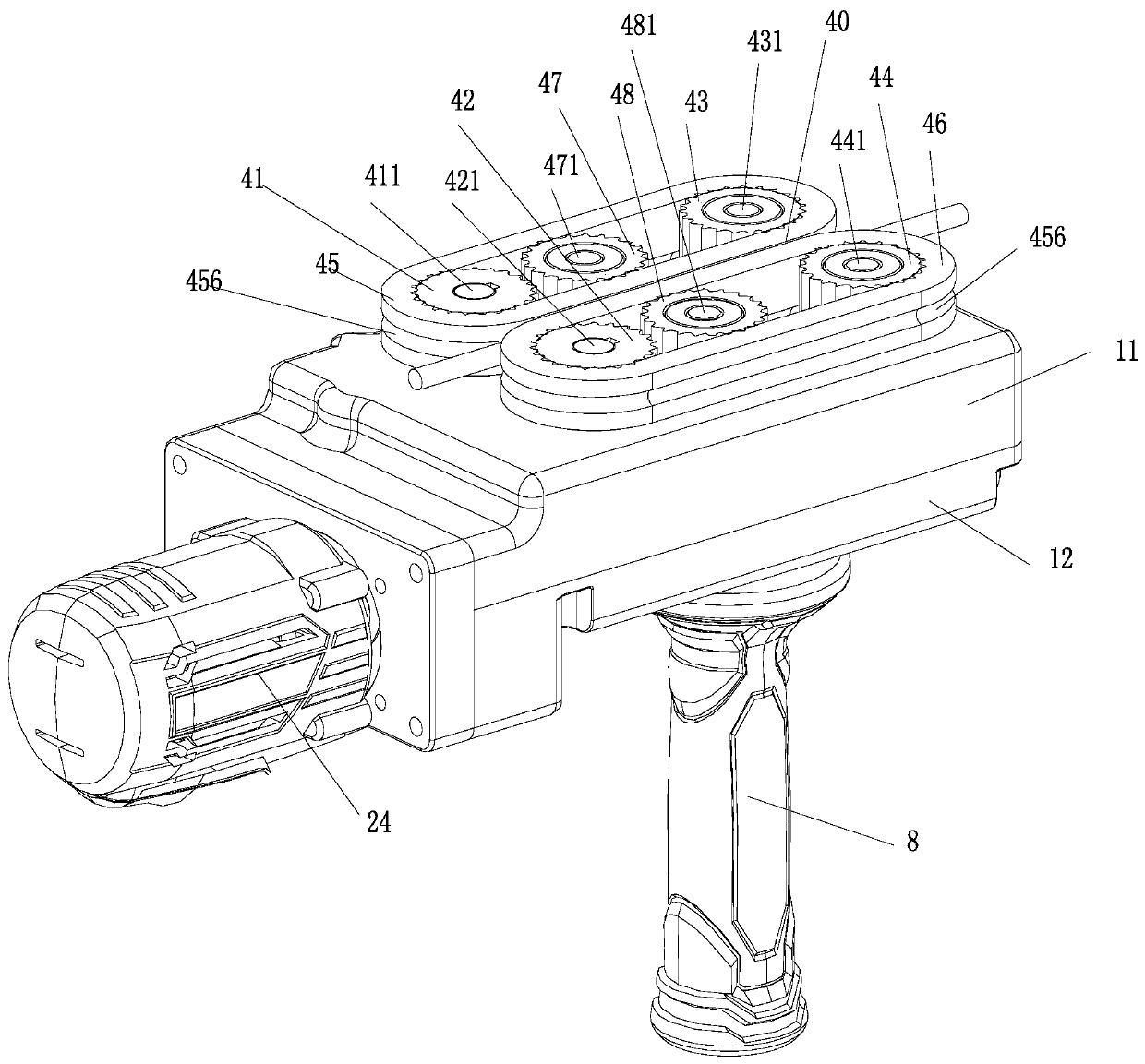
[0040] Embodiment 1: refer to Figure 1-15 . A preferred embodiment of a threading machine according to the present invention includes a body 1 and a driver 2, a transmission assembly 3 is arranged inside the body 1, the driver 2 is connected to the transmission assembly 3 by transmission, and a threading guide assembly 4 is provided at the upper end of the body 1. The threading guide assembly 4 comprises a left driving pulley 41, a right driving pulley 42, a left driven pulley 43, a right driven pulley 44, a left synchronous belt 45, and a right synchronous belt 46. There are left driving pulley 41 and right driving pulley 42 arranged longitudinally, the upper end left driving pulley 41 rear side of body 1 is provided with left driven pulley 43, and right driving pulley 42 rear side is provided with right driven pulley 44, left driving pulley 41 and left driven pulley 43 overcoats are provided with left synchronous belt 45, right driving pulley 42 and right driven pulley 44 ...

Embodiment 2

[0048] Embodiment 2: refer to Figure 10-15 . On the basis of embodiment 1. The left driven pulley 43, the right driven pulley 44 and the left middle pulley 47 and the right middle pulley 48 that are added are passed through the left driven shaft 431, the right driven shaft 441 and the left middle driven shaft 471, the right middle slave The moving shaft 481 is used to adjust the distance between threading gaps, and the adjustment mechanism involved is replaced by a structure that uses the adjustment block 100, the adjustment screw 101 and the adjustment handle 103 to complete the adjustment. Compared with Embodiment 1, the structure of this solution is simpler and more practical. The production and processing are simple, the production cost is lower, and in actual use, the operation is simpler and more in line with the requirements of actual use and usage habits. This solution is also the optimal solution. The specific technical solution is as follows:

[0049] Technical so...

Embodiment 3

[0052] Embodiment 3: In the above embodiment 1 or 2, it involves bearings provided on multiple shaft ends, and the corresponding positions of the upper casing and the lower casing of the machine body are respectively provided with bearing installation positions 111, and the bearings are fixed through the bearing installation positions. The bearings involved are not marked and described one by one in this embodiment, and the rectangles at both ends of the shafts or the simplified bearings in the drawings are indicated by reference numeral 10 .

[0053] On the basis of the above-mentioned embodiment 1 or 2, the power output end of the motor 21 can also be directly connected to the transmission shaft 31 through the coupling 211 without passing through the intermediate transmission assembly 5, and the coupling and the transmission shaft can be directly docked or The purpose of transmission through a worm gear drive connection.

[0054] On the basis of the above-mentioned embodimen...


PUM


Abstract

The invention relates to a threading machine. The threading machine comprises a machine body and a driver, wherein the machine body is internally provided with a transmission component; the driver isin transmission connection with the transmission component; the upper end of the machine body is provided with a threading guiding component; the threading guiding component comprises a left synchronous belt and a right synchronous belt; a left driving pulley and a right driving pulley arranged longitudinally are arranged on two sides of the upper end of the machine body respectively; a left driven pulley is arranged on the right side of the left driving pulley at the upper end of the machine body, and a right driven pulley is arranged on the rear side of the right driving pulley at the upperend of the machine body; the synchronous belt is arranged outside the left driving pulley and the left driven pulley; the right synchronous belt is arranged outside the right driving pulley and the right driven pulley; and a gap between the left synchronous belt and the right synchronous belt serves as a threading gap. According to the threading machine, the synchronism of a traction threading lead is high, synchronous traction of a cable is carried out through mutual clamping of the left synchronous belt and the right synchronous belt, in the transmission process, power needs to be output tothe left driving pulley and the right driving pulley, and the left driven pulley, the right driven pulley, an additional left intermediate pulley and an additional right intermediate pulley are drivenby the synchronous belts.

Description

technical field [0001] The invention belongs to the field of manufacturing cable guiding and threading equipment, and in particular relates to a threading machine. Background technique [0002] In the prior art, for example, the patent publication number is: CN208623240U, which discloses a threading mechanism of a threading machine, which includes a box body, and a worm is threaded inside the box body, and a left worm drive assembly and a right worm gear are respectively engaged on both sides of the worm. The transmission assembly, the right worm gear transmission assembly includes a right worm gear that is rotatably arranged in the box body, and the right traction wheel is arranged above the right worm gear; the left worm gear transmission assembly includes an inner box, and the inner box is rotatably arranged on the worm and can be opposed to the worm Rotate, the inner box is provided with a left turbine, the left traction wheel is arranged above the left turbine, and the ...

Claims


Application Information

Patent Timeline
IPC IPC(8): H02G1/06H02G1/08
CPCH02G1/06H02G1/081
Inventor 吕华武
Owner 永康市闳骏机电有限公司
Why Eureka
Try Eureka