Resistivity measurement cell measuring electrical resistivity anisotropy of unsaturated soil

A measuring unit and resistivity technology, applied in the direction of measuring resistance/reactance/impedance, measuring electrical variables, measuring devices, etc., can solve the problem of expensive, difficult, and inability to measure resistivity anisotropy in unsaturated soils with anisotropic resistivity And other issues

Active Publication Date: 2019-07-16
THE HONG KONG UNIV OF SCI & TECH
View PDF5 Cites 0 Cited by
  • Summary
  • Abstract
  • Description
  • Claims
  • Application Information

AI Technical Summary

Problems solved by technology

Existing methods for measuring anisotropic resistivity are expensive or difficult for unsaturated soils
The traditional four-electrode method can only measure the apparent resistivity of soil but cannot measure the anisotropy of resistivity

Method used


Image

  • Resistivity measurement cell measuring electrical resistivity anisotropy of unsaturated soil
  • Resistivity measurement cell measuring electrical resistivity anisotropy of unsaturated soil
  • Resistivity measurement cell measuring electrical resistivity anisotropy of unsaturated soil

Examples


Embodiment 1

[0049] Embodiment 1. A resistivity measurement unit, comprising:

[0050] a first measurement array arranged in a first direction; and

[0051] a second measurement array arranged in a second direction,

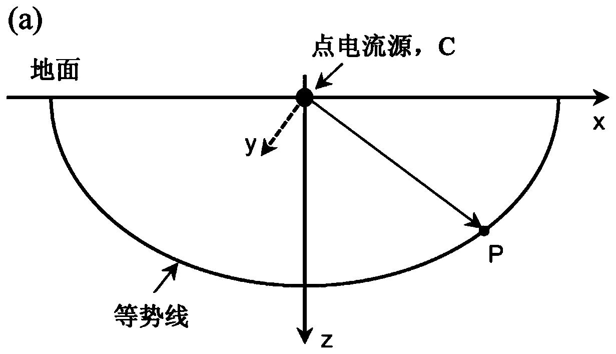
[0052] Wherein, the second measurement array includes a first point current source, a second point current source, a first point potential electrode, and a second point potential electrode; and

[0053] Wherein, in the third direction, each of the first point potential electrode and the second point potential electrode is placed at a measurement depth different from that of each of the first point current source and the second point current source (for example , in the third direction, the measurement depth of the first point potential electrode and the second point potential electrode may be lower than the measurement depth of the first point current source and the second point current source).

Embodiment 2

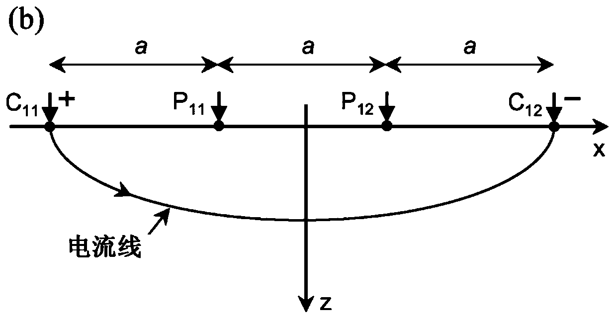
[0054] Embodiment 2. The resistivity measurement cell according to embodiment 1, wherein the first point current source, the first point potential electrode, the second point potential electrode and the second point potential electrode are arranged in any type of array (for example, in series). current source.

Embodiment 3

[0055] Embodiment 3. The resistivity measurement unit according to any one of embodiments 1-2, wherein the horizontal spacing in the second direction between the first point current source and the first point potential electrode is the same as that between the first point current source and the first point potential electrode. The vertical spacing in the third direction between the first point potential electrodes is the same.


PUM


Abstract

A resistivity measurement cell includes a first four-probe array (M1) including a first array first point current source (C11), a first array second point current source (C12), a first array first point potential electrode (P11), and a first array second point potential electrode (P 12) in a first direction; and a second four-probe array (M2) including a second array first point current source (C21), a second array second point current source (C22), a second array first point potential electrode (P21), and a second array second point potential electrode (P22) in a second direction, wherein each distal end of the first array first point potential electrode (P11) and the first array second point potential electrode (P12) is placed at a different plane from each distal end of the second arrayfirst point potential electrode (P 21) and the second array second point potential electrode (P22) in a third direction.

Description

[0001] Cross References to Related Applications [0002] This application claims priority to U.S. Provisional Patent Application No. 62 / 497,046, filed November 08, 2016, the disclosure of which is incorporated herein by reference in its entirety, including any figures, tables, or drawings. Background technique [0003] During the process of soil subsidence or compaction, fabric anisotropy is gradually formed because it is mainly affected by the arrangement tendency of non-spherical particles. Fabric anisotropy in turn leads to anisotropic responses of flow-related soil properties, such as resistivity (electrical conductivity) anisotropy, thermal conductivity anisotropy, and permeability (hydraulic conductivity) anisotropy. Because all of these flow phenomena are similar processes, and among the flow-related properties of these unsaturated soils, resistivity is relatively easy to measure, so soil resistivity is often used to assist in predicting other flow characteristics, such...

Claims


Application Information

Patent Timeline
Patent Type & Authority Applications(China)
IPC IPC(8): G01R27/14
CPCG01N27/043G01N33/24G01R27/14
Inventor 牛起飞伍玉鑫王幼行赵俊康
Owner THE HONG KONG UNIV OF SCI & TECH
Why Eureka
Try Eureka