Multi-focal structured illumination microscopy systems and methods

A microscope system, focal length technology, used in microscopy, fluorescence/phosphorescence, instrumentation, etc., to solve problems such as being unsuitable for thick or highly stained

Active Publication Date: 2019-07-16
UNITED STATES OF AMERICA
View PDF5 Cites 3 Cited by
  • Summary
  • Abstract
  • Description
  • Claims
  • Application Information

AI Technical Summary

Problems solved by technology

However, such optical sectioning is performed computationally and thus suffers from shot (Poisson) noise
Therefore, SIM is not suitable for thick or highly stained samples when background fluorescence may cause this shot noise contribution to outweigh the in-focus signal

Method used


Image

  • Multi-focal structured illumination microscopy systems and methods
  • Multi-focal structured illumination microscopy systems and methods
  • Multi-focal structured illumination microscopy systems and methods

Examples


Embodiment Construction

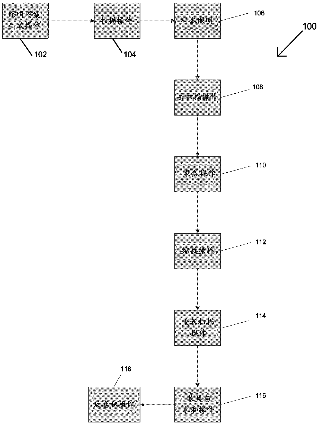
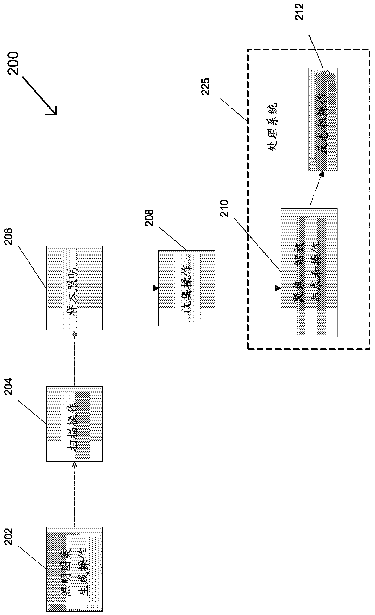
[0041] In modern microscopy, structured illumination microscopy (SIM) can be used to examine individual cells by using spatially patterned light to excite sample fluorescence to be detected later, and to process one or more images to yield resolution Super-resolution images that are twice the size of traditional wide-field microscopy images. However, the SIM system sacrifices speed (taking multiple raw images for each super-resolution image) for higher resolution. Furthermore, optical sectioning in SIM systems is performed computationally and thus prone to the shot noise inherent in the fluorescent background. This limits the thickness of samples that can be examined, requiring the use of other microscopic techniques when examining thicker samples. For example, confocal microscopy systems physically reject out-of-focus light using a pinhole arrangement that allows only light from a specific focal point of the emitted light emitted by the sample to be detected by the system, t...


PUM

PropertyMeasurementUnit
depthaaaaaaaaaa
thicknessaaaaaaaaaa

Abstract

Various embodiments (300, 400, 500) for a multi-focal selective illumination microscopy (SIM) system for generating multi-focal patterns of a sample are disclosed. The embodiments (300, 400, 500) of the multi-focal SIM system perform a focusing, scaling and summing operation on each generated multi-focal pattern in a sequence of multi-focal patterns that completely scan the sample to produce a high resolution composite image.

Description

technical field [0001] This document relates to multi-focal structured illumination microscopy, and in particular to multi-focal structured illumination microscopy systems for producing multiple multi-focal fluorescent emissions arising from a multi-focal pattern of a sample and methods. Background technique [0002] Classical fluorescence microscopy is limited in resolution by the wavelength of light, known as the "diffraction limit," which will laterally resolve a sample at typical excitation and emission wavelengths when it emits fluorescence that is detected by the microscope. The rate is limited to about 200 nm, and the axial resolution is limited to about 500 nm. Confocal microscopy is an optical imaging technique used to eliminate out-of-focus emission from specimens thicker than the focal plane by using point illumination and a spatial pinhole arrangement to Increasing the optical resolution beyond the diffraction limit delivers an image with 1.41 times the resolut...

Claims


Application Information

Patent Timeline
Patent Type & Authority Applications(China)
IPC IPC(8): G02B21/00G01N21/64
CPCG02B21/0044G02B21/0048G02B21/0036G02B21/008G02B21/0032G02B21/0076G02B21/006G01N21/6458G01N2021/6478G01N2201/105G02B21/004
Inventor H.史罗夫A.约克
Owner UNITED STATES OF AMERICA
Why Eureka
Try Eureka