Electrical DC switching system

A switching system, electrical technology, applied in electrical switches, high-voltage/high-current switches, electrical components, etc., to reduce the processing of hot gas and arc energy, reduce the risk of arc re-ignition, and reduce arc discharge time.

Active Publication Date: 2019-07-16
ABB (SCHWEIZ) AG
View PDF3 Cites 0 Cited by
  • Summary
  • Abstract
  • Description
  • Claims
  • Application Information

AI Technical Summary

Problems solved by technology

Also, simulating zero crossings provides only one chance of successfully extinguishing the arc and thus interrupting the arc current

Method used


Image

  • Electrical DC switching system
  • Electrical DC switching system
  • Electrical DC switching system

Examples


Embodiment Construction

[0036] The inventive concept will now be described more fully hereinafter with reference to the accompanying drawings, in which exemplary embodiments are shown. However, the inventive concepts may be embodied in many different forms and should not be construed as limited to the embodiments set forth herein; rather, these embodiments are provided by way of example so that this disclosure will be thorough and complete, and the present The scope of the inventive concept fully conveys to those skilled in the art. Like numbers refer to like elements throughout the specification.

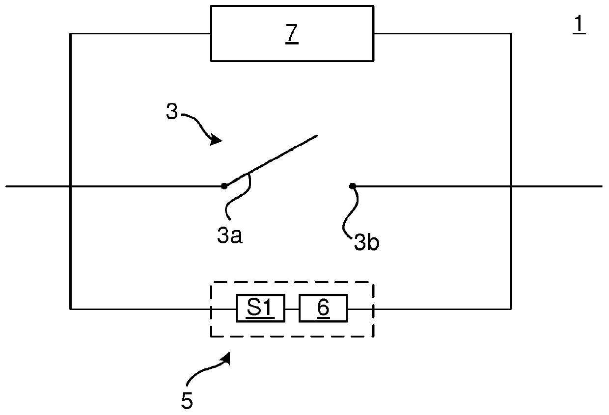
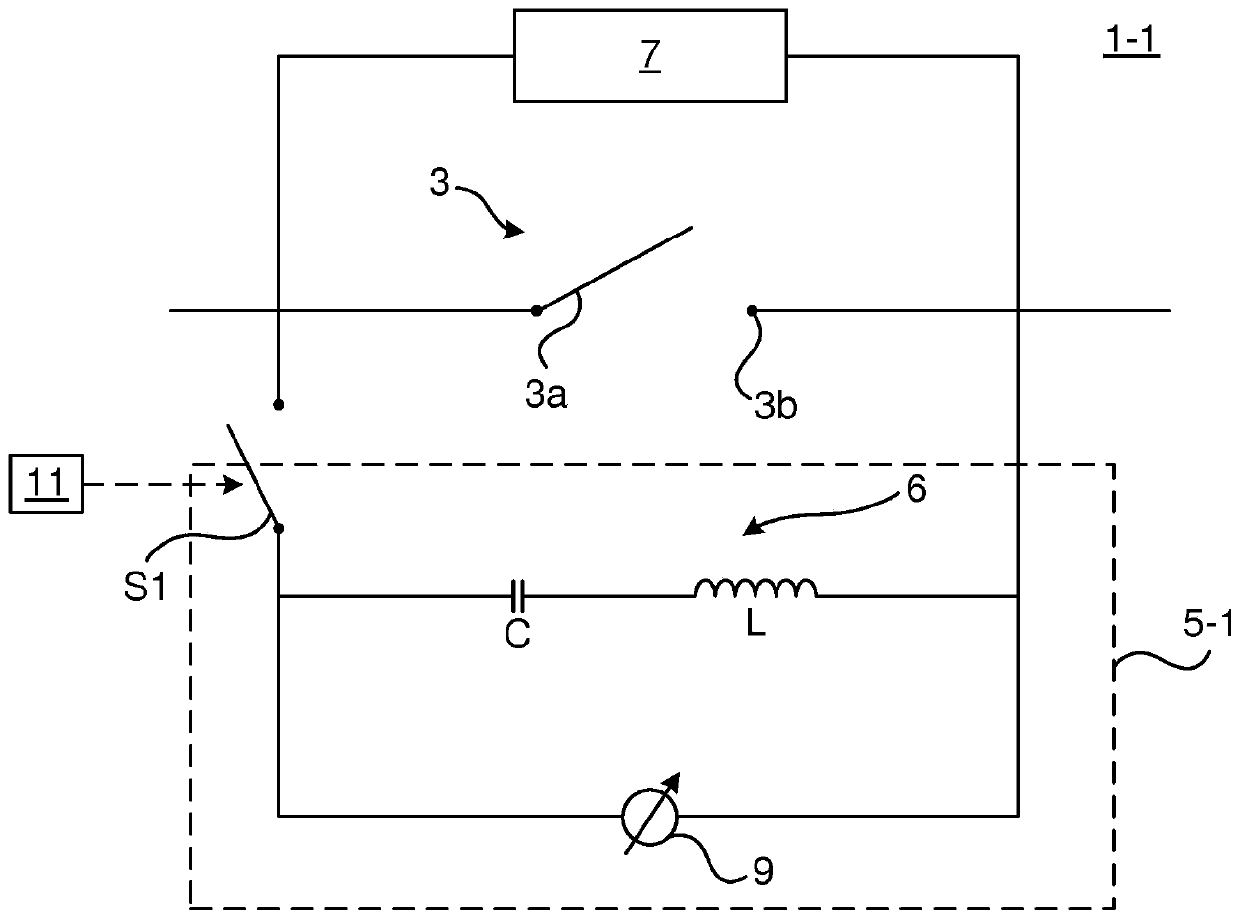
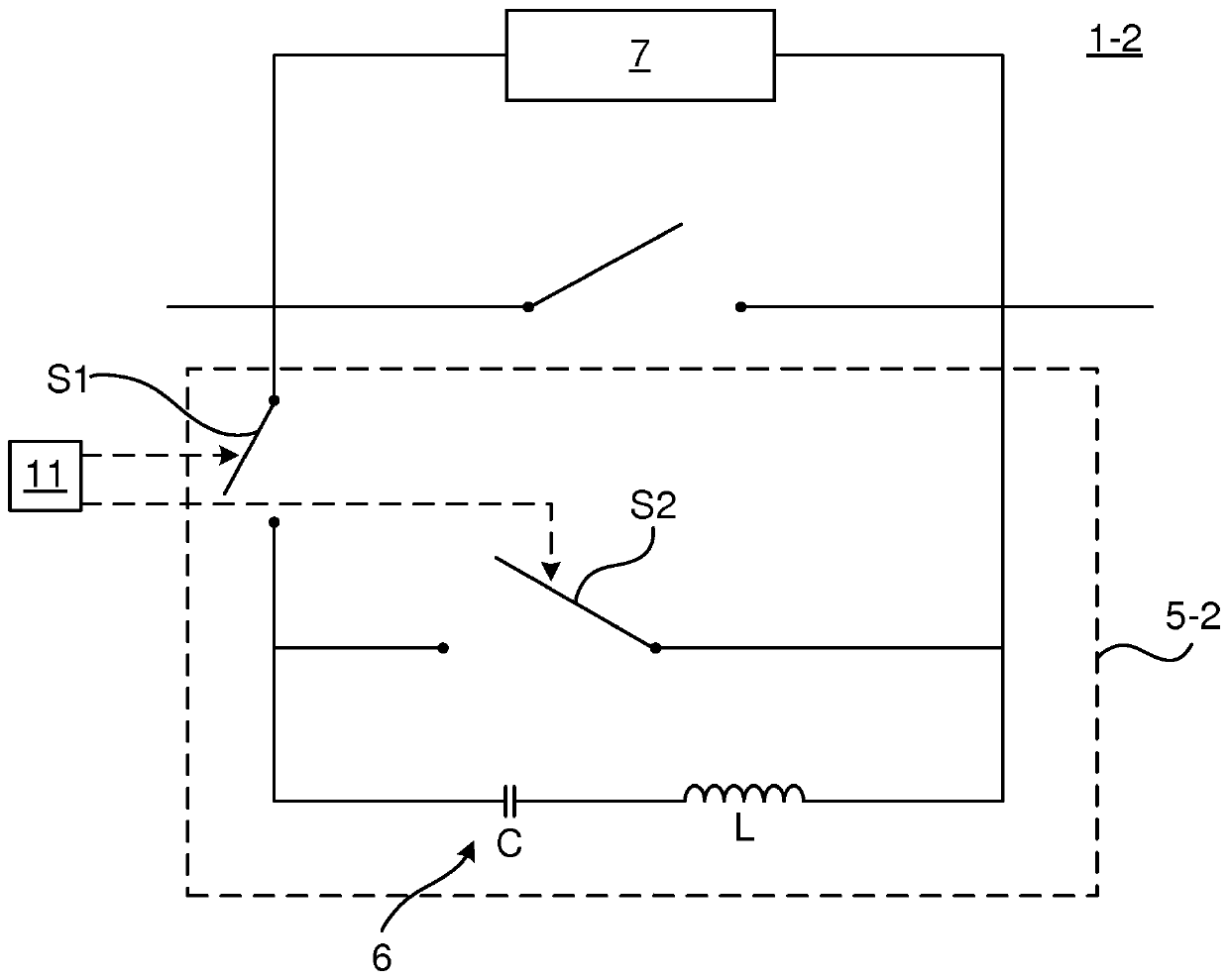
[0037] Several variations of electrical DC switching systems for breaking current will be described herein. An electrical DC switching system includes a contact arrangement having a movable circuit breaker contact and a fixed contact. The circuit breaker contacts are actuatable between a closed position, in which they are in mechanical contact with the fixed contacts, and an open position, in which they...


PUM


Abstract

The present disclosure relates to an electrical DC switching system (1) for extinguishing an electric arc, wherein the electrical DC switching system comprises: a contact arrangement (3) having a first contact (3a) and a second contact (3b), a current injection circuit (5) including a resonance circuit configured to be connected across the contact arrangement (3), and a first switch connected to the resonance circuit (6) and to the first contact (3a), wherein the first switch (S1) is configured to be switched between an open state and a closed state, wherein in the closed state the first switch is configured to enable an injection current to flow through the resonance circuit (6) in a first flow direction and into the contact arrangement (3) in a direction opposite to a flow direction of acontact arrangement arc current, and an arc chute assembly (7) comprising a plurality of splitter plates configured to extinguish an electric arc across the first contact (3a) and the second contact(3b), wherein each splitter plate of the plurality of splitter plates has a layered configuration comprising a magnetic layer and two non-magnetic layers.

Description

technical field [0001] The present disclosure relates generally to electrical DC switching systems for extinguishing arcs, and more particularly to electrical DC switching systems that rely on simulated zero crossings for arc extinguishing purposes. Background technique [0002] Switching systems are used to interrupt the current flow or to protect electrical circuits in the event of an electrical fault, for example due to a short circuit. A switching system may include contacts that are in mechanical connection during normal operation. When the contacts are separated from each other, a current breaking operation is realized. In addition to separating the contacts, the current breaking operation includes extinguishing the arc between the contacts and forcing the current to zero. [0003] Alternating current (AC) switching systems utilize the inherently occurring zero crossings of the alternating current flowing through the switching system to extinguish the arc. [0004] ...

Claims


Application Information

Patent Timeline
Patent Type & Authority Applications(China)
IPC IPC(8): H01H9/36H01H33/59
CPCH01H9/36H01H33/596H02H3/021H02H3/087H01H33/10H02H3/16
Inventor E·约翰森张自驰S·瓦德玛森
Owner ABB (SCHWEIZ) AG
Why Eureka
Try Eureka