Multi-functional manipulator

A multi-functional manipulator and mechanical claw technology, applied in the field of machinery, can solve the problem of single function of the manipulator, and achieve the effect of eliminating manual oiling

Pending Publication Date: 2019-07-19
泸州开士乐工程技术有限责任公司
View PDF0 Cites 3 Cited by
  • Summary
  • Abstract
  • Description
  • Claims
  • Application Information

AI Technical Summary

Problems solved by technology

[0003] The purpose of the present invention is to provide a multi-functional manipulator, which controls the mechanical claw by clamping the oil cylinder and the clamping synchronous link mechanism, and changes the position and structure of the mechanical claw to meet the operating requirements under different environmental conditions. Solve the problem of single function of traditional manipulator

Method used


Image

  • Multi-functional manipulator
  • Multi-functional manipulator
  • Multi-functional manipulator

Examples


Embodiment 1

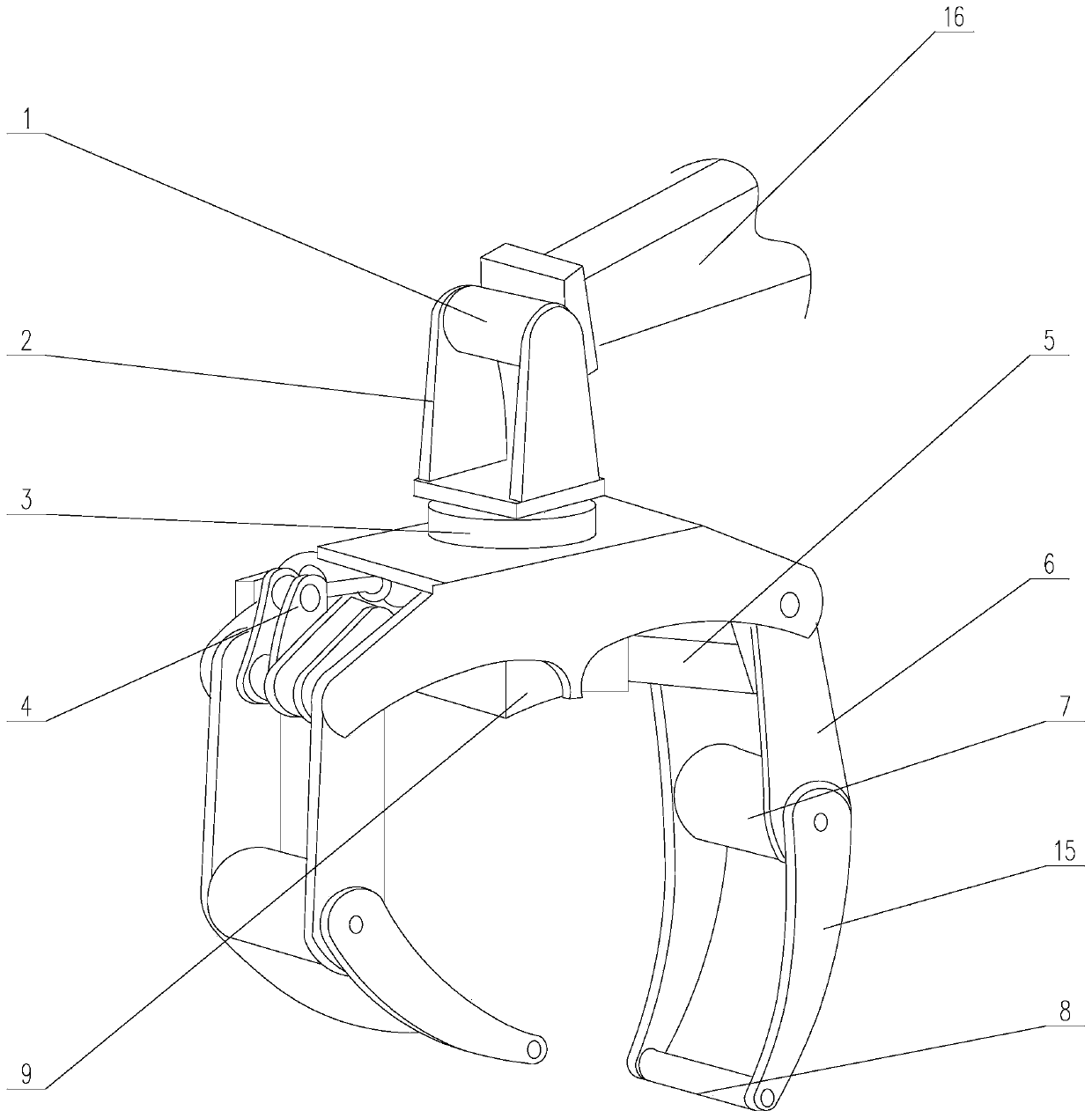
[0039] A multifunctional manipulator, comprising a folding arm 16, a rotary joint 1, an upper support 2, a rotary joint 3, a lower frame 13, a clamping oil cylinder 4, a clamping synchronous link mechanism 5, mechanical claws, a chain saw 12, and a chain Saw mount 11;

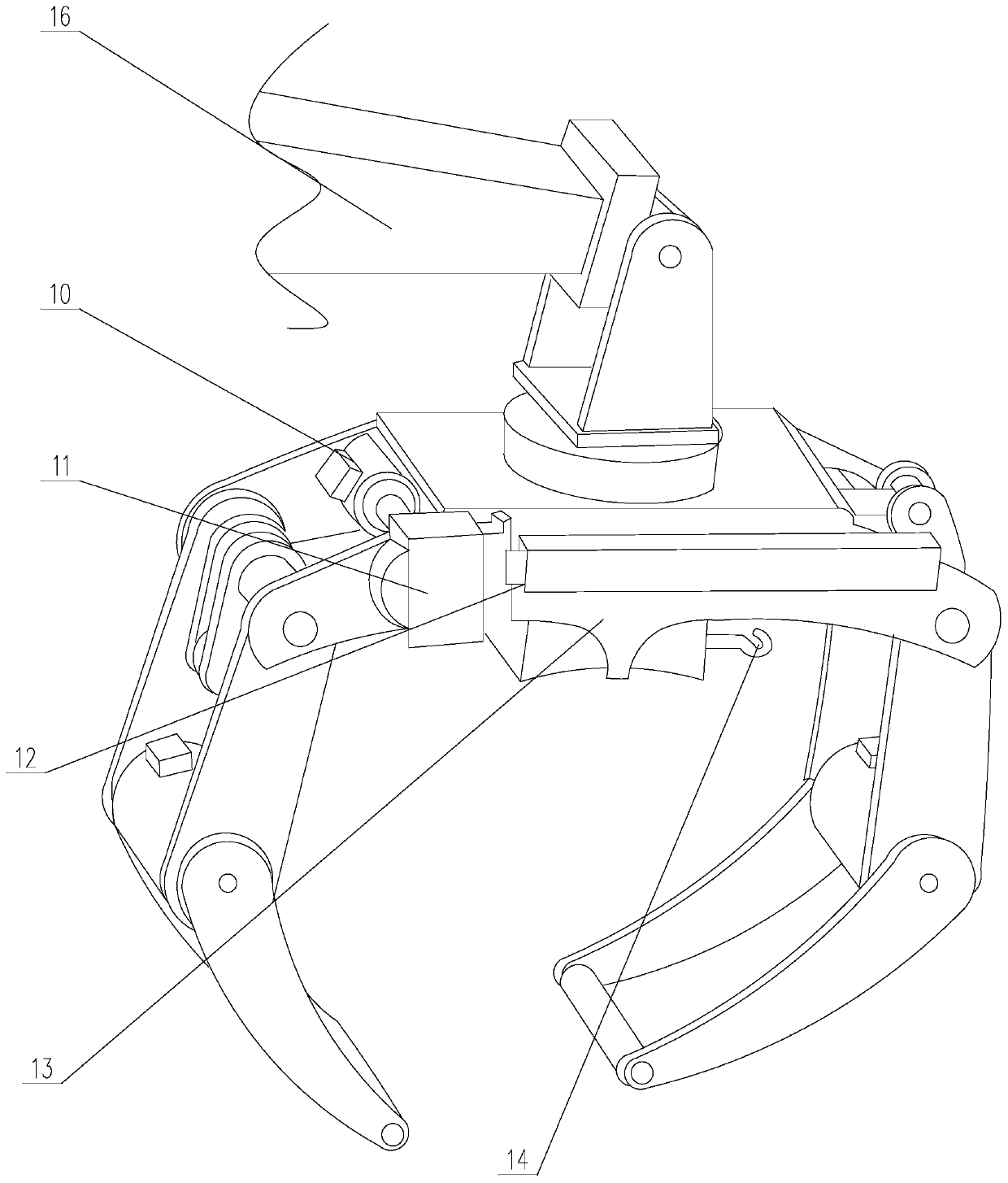
[0040] One end of the folding arm 16 is connected to the upper support 2 through the rotary joint 1, the upper support 2 is connected to the lower frame 13 through the rotary joint 3, the clamping cylinder 4 is installed on the lower frame 13, and the clamping cylinder 4 Cooperating with mechanical claws, the chain saw joint 10 is installed on the side of the lower frame 13, the chain saw 12 is connected with the chain saw joint 10 through the chain saw mounting seat 11, and a lifting hook 14 is arranged on the side of the lower frame 13 close to the ground ;

[0041] There are two mechanical claws, and the two mechanical claws are installed on the left and right ends of the lower frame 13 respectively. One me...

Embodiment 2

[0045] Such as Figure 4 As shown, the operator turns the chain saw 12 to the opposite side of the spare tire close to the side of the bin to ensure that the chain saw 12 will not collide with the side of the bin when the spare tire is grasped. Combining actions of the chain saw joint 10 , the rotary joint 1 and the rotary joint 3 further expands the working space range of the chain saw and improves its cutting capacity to meet the operating requirements in different environments.

Embodiment 3

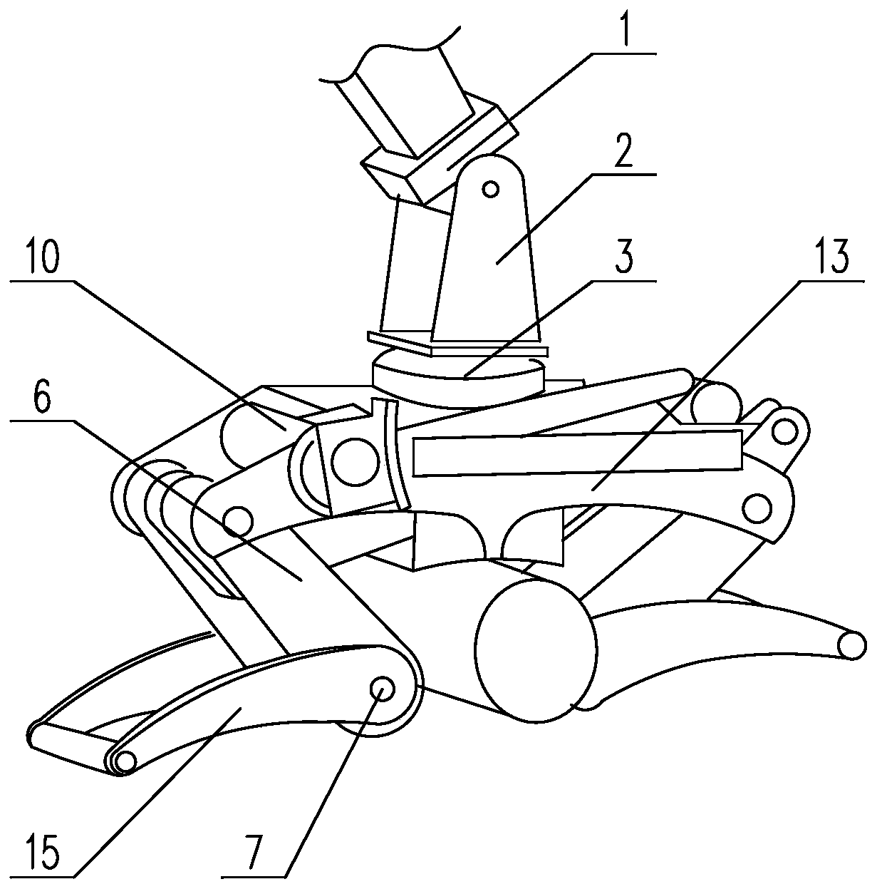
[0047] Such as image 3As shown, the operator can combine various clamping operation modes by manipulating the rotary joint 1, the rotary joint 3, the finger joint 7 and the clamping cylinder 4, etc., to realize the clamping operation of trees and the like. According to the limitation of space size, the maximum diameter of the multi-functional manipulator holding clamp is 1500mm, and the minimum diameter is 25mm.


PUM


Abstract

The invention discloses a multi-functional manipulator. The multi-functional manipulator comprises a folding arm, a rotating joint, an upper supporting seat, a rotation joint, a lower frame, a clamping oil cylinder, a clamping synchronous connecting rod mechanism, two mechanical claws, a chain saw and a chain saw installing seat; one end of the folding arm is connected with the upper supporting seat through the rotating joint, and the upper supporting seat is connected with the lower frame through the rotation joint; the clamping oil cylinder is installed on the lower frame; the chain saw is installed on the side face of the lower frame, and the chain saw is connected with a chain saw joint through the chain saw installing seat; a lifting hook is arranged on the side, close to the ground,of the lower frame; the two mechanical claws are correspondingly installed at the left end and the right end of the lower frame, and a mechanical claw is connected with the other mechanical claw through the clamping synchronous connecting rod mechanism; and the mechanical claws comprise upper claw fingers, finger joints and lower claw fingers, and the upper claw fingers are rotatably connected with the lower claw fingers through the finger joints. The problem that the function of a traditional manipulator is single is solved by the multi-functional manipulator.

Description

technical field [0001] The invention relates to the mechanical field, in particular to a multifunctional manipulator. Background technique [0002] There are various kinds of mechanical claws on the market, but the shape of the claws of the mechanical claws is fixed, so that the function of the mechanical claws is very single, and can only be used for specialized technical operations. When other technical operations are required, they must be replaced. The working process of different mechanical claws is very cumbersome, and now it is necessary to improve the mechanical claws to meet the operating requirements under different environmental conditions. Contents of the invention [0003] The purpose of the present invention is to provide a multi-functional manipulator, which controls the mechanical claw by clamping the oil cylinder and the clamping synchronous link mechanism, and changes the position and structure of the mechanical claw to meet the operating requirements und...

Claims


Application Information

Patent Timeline
IPC IPC(8): B25J15/00B25J15/08B25J9/10B25J17/00B25J19/02
CPCB25J15/00B25J15/08B25J17/00B25J9/104B25J19/02
Inventor 经廷辉王文富夏志余绪洋
Owner 泸州开士乐工程技术有限责任公司
Why Eureka
Try Eureka