Robot power cable guiding device and system thereof

A power cable and guiding device technology, which is applied in the direction of manipulators, manufacturing tools, etc., can solve the problems that the cables are not easy to move freely, difficult to turn, etc., and achieve the effect of reducing surface scratches, reducing friction, and simple structure

Inactive Publication Date: 2019-07-19
郑州心忠圆科技有限公司
View PDF6 Cites 3 Cited by
  • Summary
  • Abstract
  • Description
  • Claims
  • Application Information

AI Technical Summary

Problems solved by technology

[0004] The purpose of the present invention is to provide a robot power cable guiding device and its system in order to solve the problems in the prior art that the power cable is not easy to move freely and turn when it is guiding, turning and going.

Method used


Image

  • Robot power cable guiding device and system thereof
  • Robot power cable guiding device and system thereof
  • Robot power cable guiding device and system thereof

Examples


Embodiment example 1

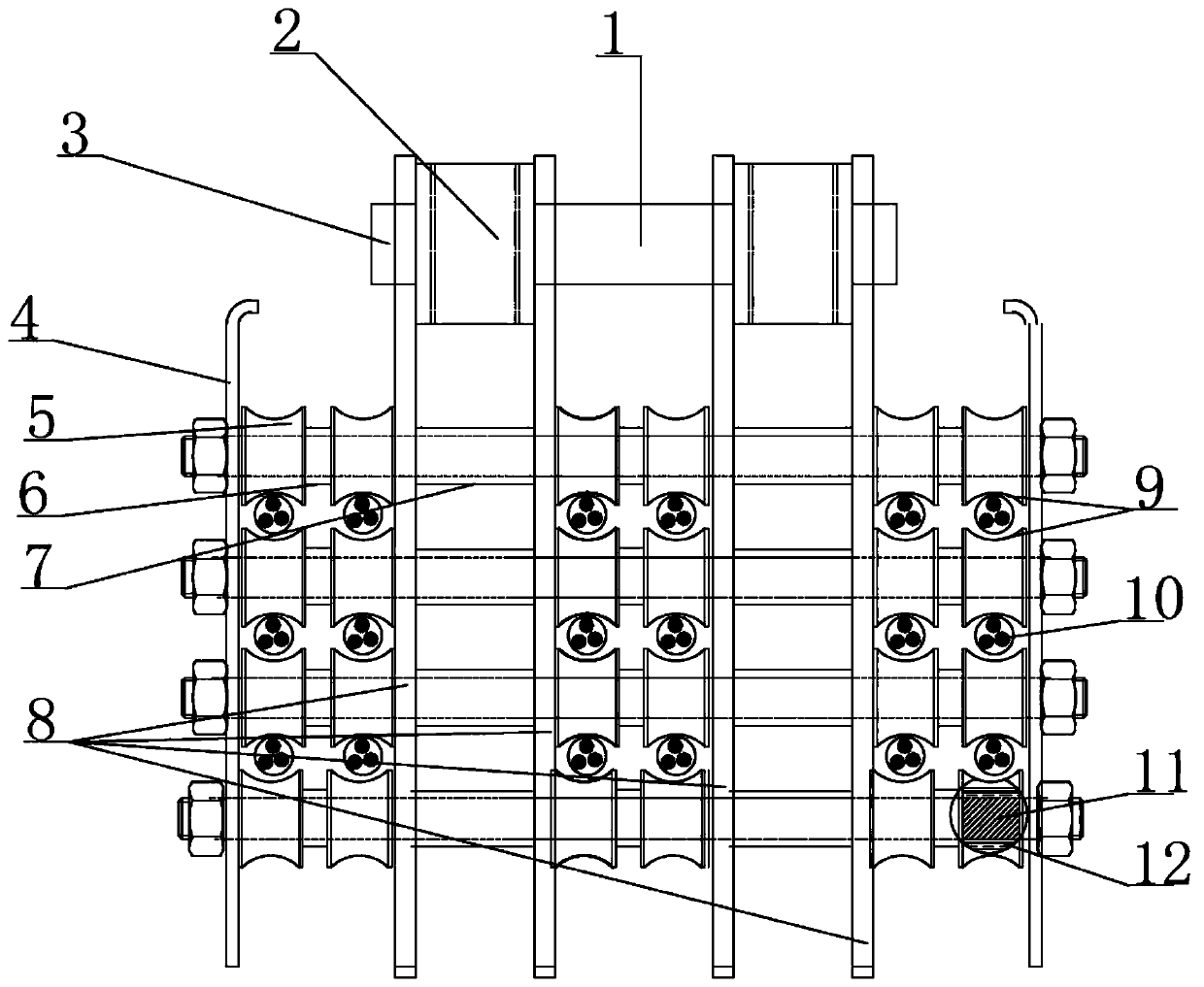
[0039] Implementation case 1: A guiding device for a robot power cable 10, including a body, the body includes four symmetrically arranged substrates 8, a first through hole is arranged on the upper side of the substrate 8, and a first rotating shaft 1 is arranged in the first through hole. The first rotating shaft 1 is provided with a first roller 3, the lower side of the base plate 8 is provided with a second through hole, and a second rotating shaft 11 is arranged in the second through hole, and a plurality of bearings 12 are arranged on the second rotating shaft 11, and the bearings 12 are put on A second roller 5 is provided.

[0040] Such as Figure 4 As shown, the second roller 5 is provided with an arc-shaped groove 9, and an arc-shaped surface is arranged in the arc-shaped groove 9. The arc-shaped design surface of the arc-shaped groove 9 is a good contact surface for cables, and is suitable for When the cable slides on the second roller 5, a grease hole 13 is provid...

Embodiment example 2

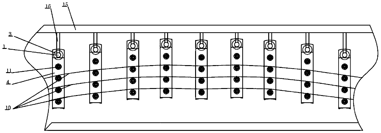
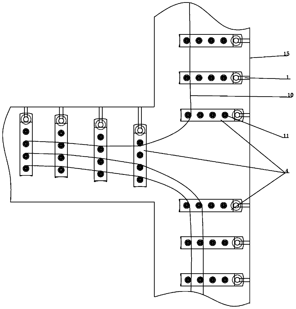
[0044] Implementation Case 2: If figure 1 , figure 2 and image 3 As shown, a robot power cable 10 guiding system includes a pipeline 15 and a power cable 10. The power cable 10 is arranged in the pipeline 15, and a plurality of guiding devices are arranged on the lower side of the pipeline 15. The guiding device includes a body, and the body includes Four symmetrically arranged substrates 8, the upper side of the substrate 8 is provided with a first through hole, the first through hole is provided with a first rotating shaft 1, the first rotating shaft 1 is provided with a first roller 3, and the lower side of the substrate 8 is provided with a first Two through holes, a second rotating shaft 11 is arranged in the second through hole, a plurality of bearings 12 are arranged on the second rotating shaft 11, and a second roller 5 is set on the bearing 12, and the cable passes through the second roller 5 adjacent up and down .

[0045] The size of the first roller 3 is large...


PUM


Abstract

The invention discloses a robot power cable guiding device and a system thereof, belongs to the technical field of robot equipment. The robot power cable guiding device and the system thereof aim to solve the problems in the prior art that a power cable is not easy to move freely and not easy to turn during guiding, steering and going. The robot power cable guiding device comprises a body, whereinthe body comprises four substrates symmetrically arranged; a first through hole is formed in the upper side of each substrate; a first rotating shaft is arranged in the first through hole; a first roller is arranged on the first rotating shaft; a second through hole is formed in the lower side of each substrate; a second rotating shaft is arranged in the second through hole; a plurality of bearings are arranged on the second rotating shaft; and second rollers sleeve the bearings. Due to the design of the second rotating shaft, the bearings and the second rollers, a power cable can freely moveaccording to requirements, and the problem that the power cable is not easy to move in the prior art is solved; and an upper arc-shaped groove and a lower arc-shaped groove between the adjacent second rollers form a limiting steering mechanism, so that steering of the power cable is facilitated.

Description

technical field [0001] The invention belongs to the technical field of robot equipment, and in particular relates to a robot power cable guiding device and a system thereof. Background technique [0002] Power cables refer to cables with large wire diameters, generally three or four cores, thicker insulation between phases, and protected by metal armor on the outside. It is mainly used in the power supply system as the main line of three-phase industrial power or single-phase civil power. [0003] Existing power cables are generally fixed on the support frame. The weight of the power cables is generally heavy, and the surface of the cables is easy to be damaged when moving. During the process, it is easy to string and jump wires, which makes it easy to get stuck between multiple power cables, causing mechanical failures such as the shutdown of the robot. The existing robot power cables lack guiding and steering components, so that the power cables Large and prone to snags,...

Claims


Application Information

Patent Timeline
Patent Type & Authority Applications(China)
IPC IPC(8): B25J19/00
CPCB25J19/00
Inventor 方甲旺
Owner 郑州心忠圆科技有限公司
Why Eureka
Try Eureka