Sliding self-anchored socket and spigot joint structure

A self-anchored, plug-in connection technology, applied in the direction of sleeve/socket connection, pipe/pipe joint/pipe fitting, passing element, etc. Avoid excessive loads, reduce workload and costs, and prolong service life

Pending Publication Date: 2018-02-16
JILING YULINGLONG STEEL PIPE STEEL STRUCTURE MFG
View PDF6 Cites 0 Cited by
  • Summary
  • Abstract
  • Description
  • Claims
  • Application Information

AI Technical Summary

Problems solved by technology

[0004] 1 Pipe fittings and pipes are usually threaded, which need to be screwed in during installation, which is inefficient;
[0005] 2 Due to the large pipe diameter, long size and high sealing strength, the force required for installation is relatively large, and it is very difficult to grasp the gap between the socket and the socket. Often due to thermal expansion and contraction, it is easy to make the adjacent pipes top Dead, the pipe after the top is dead will bulge, and there is a safety hazard;
[0006] 3 If it is used in the heating pipe network, the thermal expansion of the material will cause the steel pipe to bulge when heated, which poses a safety hazard; to solve this problem, a thermal compensator is usually used to compensate the expansion and contraction of the pipeline, but because of this Increase the material cost and installation workload of the pipeline, prolong the installation time, and eventually lead to an increase in the pipeline cost of the heating pipeline network;
[0007] 3. It is difficult to adjust the coaxiality of the front pipe, pipe fittings and rear pipe after installation, resulting in uneven gaps between the front pipe, pipe fittings and rear pipe; the result is: the front pipe, pipe fitting and rear pipe are not coaxial and increase the transmission in the pipeline The resistance of the medium flow, the pressure on the pipe wall also increases, the gap between the front pipe, pipe fittings and the rear pipe is uneven, and the increase in the pressure on the pipe wall makes the local seal ring bear too much load, which is easy to produce eccentric displacement and It is easy to bear excessive load and cause failure, reduce the service life of the sealing ring, and increase the workload and cost of pipeline maintenance. The flat socket and spigot of the existing spiral welded pipe have large ellipticity, which not only increases the difficulty in the process of pipeline installation, Moreover, the sealing ring will be damaged due to the lack of guidance at the pipe end. After installation, the gap between the pipe socket and the pipe fitting will be uneven due to the ellipse of the nozzle opening, which will cause the sealing ring to bear too much load locally and reduce the sealing effect;
[0009] 5. There is no room for disassembly of the existing pipeline after installation. During the use and maintenance of the pipeline, it is often faced with the problem of replacing the pipe material, connecting a new branch line pipe or installing other pipe fittings. Or the connection method of installing other pipe fittings has the low screw connection efficiency, it is difficult to grasp the gap between the socket and the socket during installation, and when used in the heating pipe network, a thermal compensator is required to compensate the temperature difference of the pipeline, and the pipeline is prone to eccentric displacement after installation. And the failure of the sealing ring, the joint between the pipe fitting and the pipe is also prone to cracking, leakage or even detachment, which cannot meet the needs of pipeline use and maintenance

Method used


Image

  • Sliding self-anchored socket and spigot joint structure
  • Sliding self-anchored socket and spigot joint structure
  • Sliding self-anchored socket and spigot joint structure

Examples


Embodiment 1

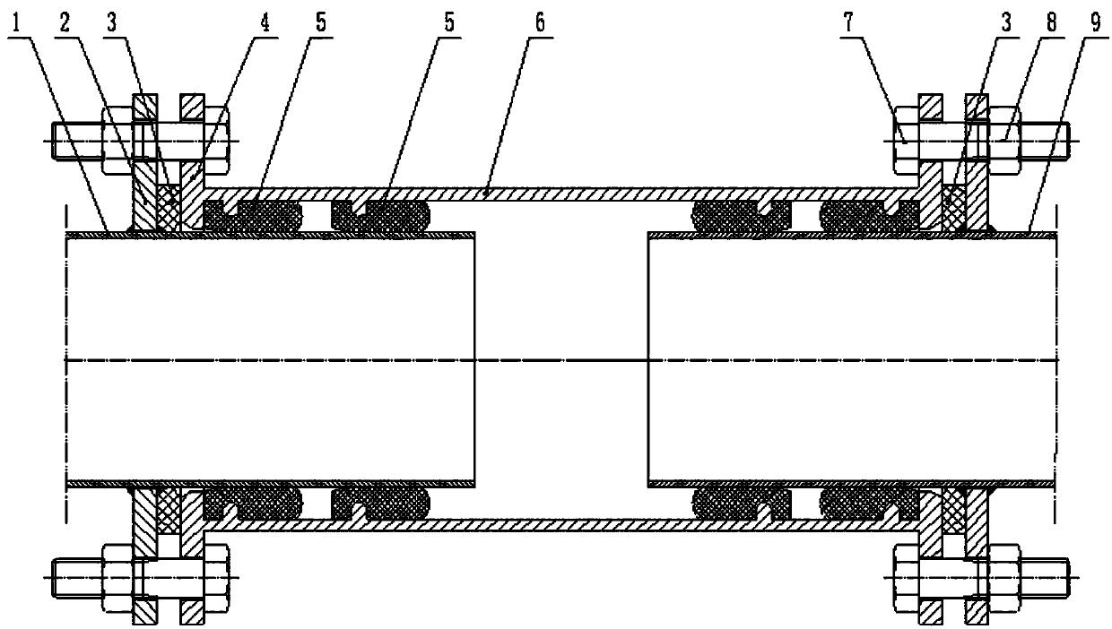
[0051] Embodiment 1, with reference to figure 1 , Embodiment 1 is a sliding-in self-anchoring socket connection structure, including a socket pipe 6, a front pipe 1, a rear pipe 9, a first sealing ring 3 and a second sealing ring 5, the inner wall of the socket pipe 6 Set four ring-shaped projections for placing the T-shaped sealing ring as the second sealing ring 5, and also include the anchoring flange 2 with the function of limiting anchoring and the guiding and anchoring ring plate with the function of guiding and anchoring 4. The anchor flanges 2 are respectively sleeved on the socket ends of the front pipe 1 / rear pipe 9 and fixedly connected, and the guide anchor ring plates 4 are respectively placed at both ends of the socket pipe 6, and the guide anchors One end surface of the fixed ring plate 4 is fixedly connected with the socket pipe 6, and the inner peripheral surface of the guide anchor ring plate 4 located in the socket pipe 6 is a guiding surface, and the part l...

Embodiment 2

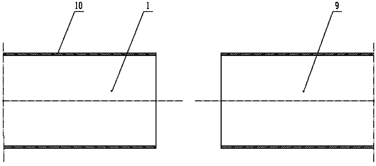
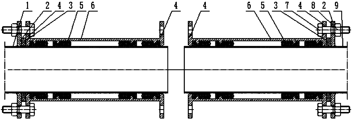
[0056] Embodiment 2, with reference to Figure 2-6 , Embodiment 2 is a sliding-in self-anchor type socket connection structure, which is used for the connection of the existing pipeline 10 to a new branch line pipe. The embodiment 2 is basically the same as the embodiment 1, except that the anchor The fixed flange 2 is sleeved on the socket end of the front pipe 1 / rear pipe 9 and is slidably connected. Its structure is: it includes the front pipe 1, the rear pipe 9, the anchor flange 2, the tee 11, and the guide and anchor ring plate 4. The socket pipe 6, the first seal ring 3 and the second seal ring 5, the socket end of the front pipe material 1 and the socket end of the rear pipe material 9 are respectively socketed on the anchor flange 2 and slidably connected, the three The two ends of the channel 11 are respectively sleeved with the anchoring flange 2 and fixedly connected, and the guiding and anchoring ring plates 4 are respectively placed at both ends of the socket pip...

Embodiment 3

[0063] Embodiment 3, embodiment 3 is a sliding self-anchoring socket connection structure, the embodiment 3 is basically the same as the embodiment 1, the difference is that the guiding section of the guiding anchor ring plate 4 is a circular arc surface .


PUM


Abstract

The invention provides a sliding self-anchored socket and spigot joint structure. The sliding self-anchored socket and spigot joint structure comprises socket pipes and is characterized by further comprising anchoring flanges and guide anchoring annular plates, wherein the anchoring flanges are fixedly connected to the socket end of a front pipe and the socket end of a rear pipe in a sleeving manner separately, and the guide anchoring annular plates are arranged at the two ends of the socket pipes separately; the end face of one side of each guide anchoring annular plate is fixedly connected with the corresponding socket pipe, and the front pipe is connected to the front ends of the socket pipes in an inserted manner; one bolt simultaneously penetrates through the anchoring flange of the front pipe, a first sealing ring, the guide anchoring annular plate of the corresponding socket pipe and the end to be anchored and fixedly connected with a nut in a threaded connection manner; the rear pipe is connected to the rear ends of the socket pipes in an inserted manner, one bolt simultaneously penetrates through the anchoring flange of the rear pipe, a first sealing ring, the guide anchoring annular plate of the corresponding socket pipe and the end to be anchored and fixedly connected with a nut in a threaded connection manner, the front pipe makes sealing contact with the socket pipes through second sealing rings arranged in the socket pipes, and the rear pipe makes sealing contact with the socket pipes through second sealing rings arranged in the socket pipes.

Description

technical field [0001] The invention relates to the field of pipelines, and is a sliding self-anchoring socket connection structure, which is used for socket connection pipes of welded steel pipes or socket connection steel-plastic composite pipes with spiral welded steel pipes as base pipes. Background technique [0002] In the pipeline installation process, it is one of the connection methods to connect the pipes sequentially through pipe fittings to form a pipe. The connection structure is: the sockets of the adjacent front pipes are plugged into the sockets of the rear pipes, and a sealing ring is set between them. The pipes are sequentially sealed and connected as pipes. [0003] The pipe fitting connection of the prior art has the following problems: [0004] 1 Pipe fittings and pipes are usually threaded, which need to be screwed in during installation, which is inefficient; [0005] 2 Due to the large pipe diameter, long size and high sealing strength, the force re...

Claims


Application Information

Patent Timeline
Patent Type & Authority Applications(China)
IPC IPC(8): F16L21/02F16L21/08
CPCF16L21/022F16L21/08
Inventor 费敏建
Owner JILING YULINGLONG STEEL PIPE STEEL STRUCTURE MFG
Why Eureka
Try Eureka