
A Tool Arbor Tailstock Clamped by Taper Set

A tool holder and tailstock technology, applied in the direction of tailstock/top, accessories of toolholders, turning equipment, etc., can solve problems such as inability to meet requirements, and achieve the effect of improving accuracy and rigidity, and improving accuracy and life.

Active Publication Date: 2016-05-18
NINGBO XIATUO MACHINERY EQUIP
View PDF7 Cites 0 Cited by
  • Summary
  • Abstract
  • Description
  • Claims
  • Application Information

AI Technical Summary

Problems solved by technology

When the tool is longer, the cutting resistance is greater, and the precision requirements are higher, this split type tool holder tailstock cannot meet the demand

Method used


Image

  • A Tool Arbor Tailstock Clamped by Taper Set
  • A Tool Arbor Tailstock Clamped by Taper Set
  • A Tool Arbor Tailstock Clamped by Taper Set

Examples


Embodiment Construction

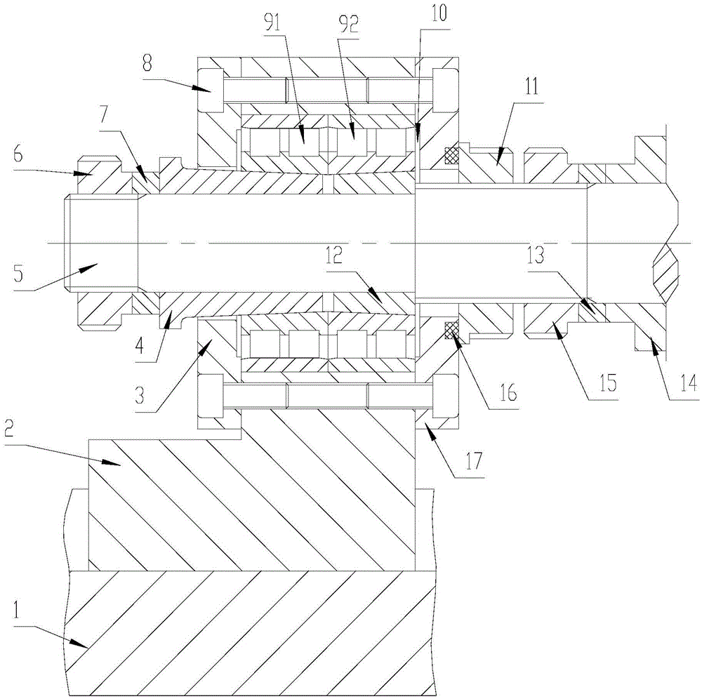
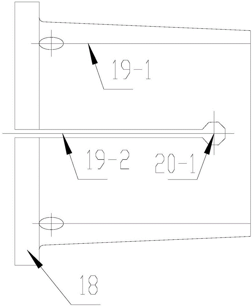
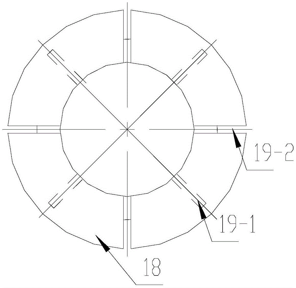
[0023] refer to Figure 1 to Figure 5 , the present invention provides a tool bar tailstock clamped with a cone sleeve, including a tailstock body 2 for supporting the tail end of the tool bar, and a tool bar 5 equipped with a tool 14, and a tailstock is provided on the tailstock body 2 body mounting hole, wherein, the first bearing 91 and the second bearing 92 whose inner hole is a tapered hole are installed in the tailstock body mounting hole, and the small diameter ends of the tapered holes of the first bearing 91 and the second bearing 92 face each other Installation, the rear end cover 3 that carries out axial positioning to the first bearing 91 and the front end cover 17 that the second bearing 92 is carried out axial positioning are respectively fixed at the two ends of the tailstock body mounting hole, in the first bearing 91 The first taper sleeve 4 is sleeved, and the second taper sleeve 12 is sleeved in the second bearing 92 (there is a gap between the opposite surf...


PUM


Abstract

The invention provides a cutter bar tailstock for clamping taper sleeves. The cutter bar tailstock is precisely clamped and assembled on a cutter bar to form a rotating body by adopting two oppositely-installed precise elastic taper sleeves and a pair of biserial cylindrical roller bearings with inner taper holes. After the tailstock with an integrated structure the cutter bar penetrates through is installed in place, the rigidity and precision of the cutter bar in work are ensured, the taper sleeves and the tailstock are quick and convenient to install and dismount, and the cutter bar tailstock is suitable for tail-end supporting of long rolling and milling rotary cutters.

Description

technical field [0001] The invention relates to a cutter bar tailstock clamped by a precision elastic cone sleeve, in particular to a cutter bar tailstock used for installing long hobbing and milling rotary cutting tools. Background technique [0002] In some cutting machine tools for hobbing and milling, hobs and milling cutters are installed on the cutter bar for rotary cutting. The front end of the tool bar is connected to the tool spindle of the machine tool to obtain the force required for cutting and the accuracy and stiffness. If the cutter is short, the motion accuracy and rigidity of the cantilever beam installation of the cutter rod can generally meet the processing requirements, but if the cutter is long, the motion accuracy and rigidity of the cutter rod tailstock are relatively low under the action of cutting resistance. The front end is descending geometrically, which obviously cannot meet the requirements of processing operations. At this time, it is necessa...

Claims


Application Information

Patent Timeline
Patent Type & Authority Patents(China)
IPC IPC(8): B23B23/00
CPCB23Q1/76
Inventor 刘大猷树军钱海张海清
Owner NINGBO XIATUO MACHINERY EQUIP
Learn More