Dynamic pressure feedback pilot control hydrodynamic shock oscillator

A technology of hydraulic impact and dynamic pressure feedback, which is applied to vibration drilling, vibration generating devices, wellbore/well components, etc. It can solve the problem of small effective working pressure difference, low maximum working pressure, and easy erosion of components. Short life and other problems, to achieve the effect of overcoming steady-state and transient hydraulic power, reliable self-excited vibration control, and avoiding mechanical energy loss

Active Publication Date: 2019-07-19
JILIN UNIV
View PDF8 Cites 4 Cited by
  • Summary
  • Abstract
  • Description
  • Claims
  • Application Information

AI Technical Summary

Problems solved by technology

Although the hydraulic jet impactor directly controlled by the bistable jet element has been improved and optimized many times, it is still difficult to fundamentally solve the problem that the components are easy to erode, the service life is short, the effective working pressure difference of the impactor is small, and the flow rate in the upper cavity of the inner cylinder is difficult during the stroke. Meet the high-speed motion requirements of piston and hammer, etc.
In fact, the root cause of the above-mentioned difficulties is that the use of jet elements to directly control the impact mechanism cannot break through the limitations of its own structure and performance.
The bistable wall-attached jet element works according to the principle of Coanda, with a narrow input channel and an open working chamber inside. Therefore, in the face of the drilling industry's work requirements of using water and mud as the working medium and high flow rate, the jet element is used directly In principle, there are insurmountable technical bottlenecks in the controlled hydraulic jet impactor, such as the extremely small flow area at the inlet of the component, which causes extremely high throttling loss, and the attached wall jet is easily unstable due to the influence of load, etc.; in addition, For its application in the field of construction machinery hydraulic vibration technology, although the jet element has the characteristics of non-moving parts and pressure feedback control, because its maximum working pressure is not high, it cannot be directly used to drive the impact mechanism to obtain high impact energy, so lose practical value

Method used


Image

  • Dynamic pressure feedback pilot control hydrodynamic shock oscillator
  • Dynamic pressure feedback pilot control hydrodynamic shock oscillator
  • Dynamic pressure feedback pilot control hydrodynamic shock oscillator

Examples


Embodiment Construction

[0025] In order to illustrate the present invention more clearly, the present invention will be further described below in conjunction with preferred embodiments and accompanying drawings. Those skilled in the art should understand that the content specifically described below is illustrative rather than restrictive, and should not limit the protection scope of the present invention.

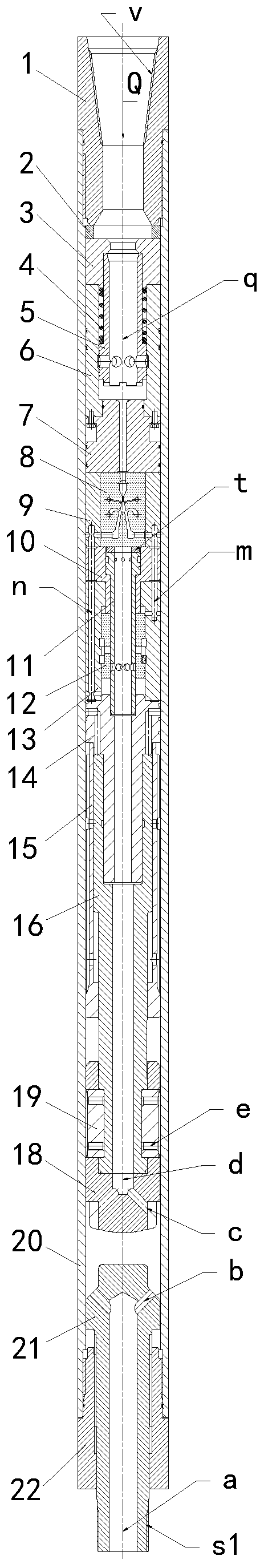
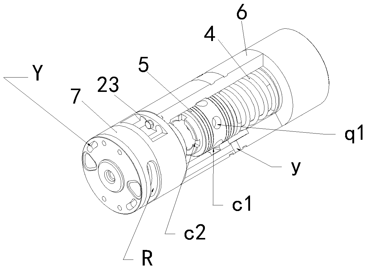
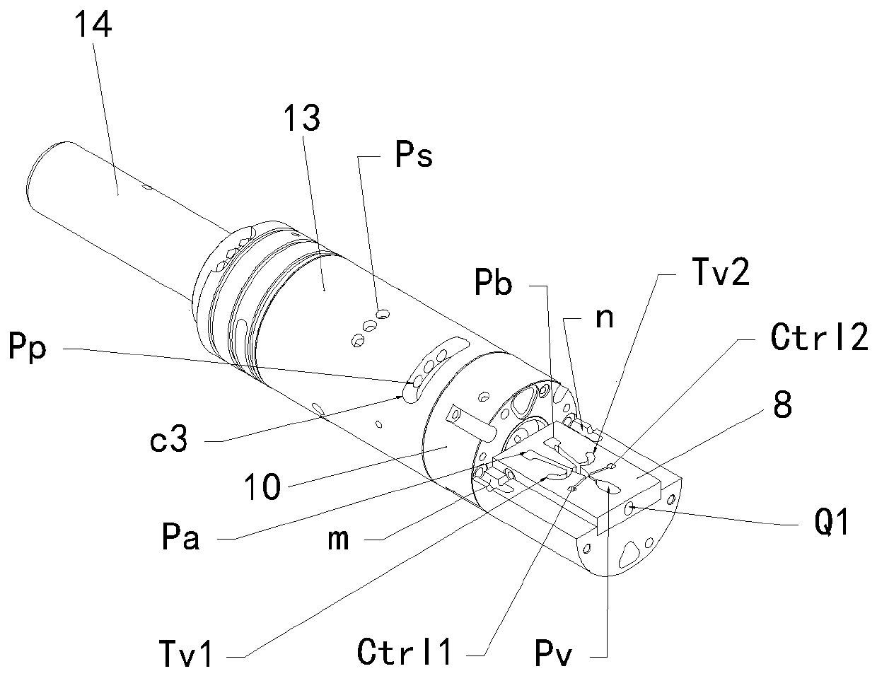
[0026] like figure 1 , figure 2 , image 3 , Figure 4 , Figure 5 and Image 6 As shown, the dynamic pressure feedback pilot control hydraulic shock oscillator proposed by the present invention adopts the bistable wall-attached jet element 8 as the pilot valve, and the reversing valve 12 as the main valve, and the reversing valve 12 controls the passage of high-pressure and large-flow liquid. The distribution channel drives the hydraulic impact mechanism to move. The constructed secondary control hydraulic impact system has the following main technical features:

[0027] (1) The flow inpu...


PUM


Abstract

The invention discloses a dynamic pressure feedback pilot control hydrodynamic shock oscillator. The dynamic pressure feedback pilot control hydrodynamic shock oscillator is a shocking oscillating device that a jet flow element is adopted as a pilot stage, two-stage composite control is formed by the jet flow element and a reversing valve, and high-pressure water or high-pressure oil carries hydraulic energy to drive high-frequency reciprocating motion of a piston. After total flow is input, the total flow is dynamically allocated to the jet flow element and the reversing valve, the flow provided for the jet flow element only needs to be met the requirements of driving a main valve core to reverse, and most of the flow is controlled by the reversing valve and supplied to a shocking mechanism. In addition, the dynamic pressure feedback pilot control hydrodynamic shock oscillator adopts a hydraulic shocking pressure signal with an internal feedback mechanism to control switching of a wall-attached jet flow, then the main valve core is pushed to reverse, high-frequency reciprocating motion of the piston of the shocking mechanism under the large flow condition is realized, and the high-energy shocking and oscillation effects are generated. The dynamic pressure feedback pilot control hydrodynamic shock oscillator can be used as a core part, can be widely applied to a rotary churn drilling tool system for hard rocks drilling in deep wells, and can also be used for constructing a hydraulic fracturing hammer, a jack-drive hydraulic pile hammer or a rammer pipe hammer and a hydraulic vibration test table.

Description

technical field [0001] The invention relates to a hydraulic shock and vibration device, in particular to a dynamic pressure feedback pilot control hydraulic shock oscillator. Background technique [0002] The proposal of the hydraulic jet impactor can be traced back to the Chinese invention patent CN2040529 in 1989. This patent discloses a hydraulic impact vibration device that uses a bistable wall-attached jet element to directly drive the piston to do work. Due to the simple structure of the whole machine, It is easy to manufacture and adopts clear water and mud as the working medium and is compatible with the drilling process. This type of product is widely used in the fields of geological exploration and oil and gas well exploration and drilling. During the specific use of the hydraulic jet impactor, many problems such as easy erosion and damage of the jet components, insufficient flow supply in the upper chamber of the inner cylinder when the piston moves at high speed,...

Claims


Application Information

Patent Timeline
Patent Type & Authority Applications(China)
IPC IPC(8): E21B7/24E21B28/00
CPCE21B7/24E21B28/00
Inventor 王清岩
Owner JILIN UNIV
Why Eureka
Try Eureka