A Refrigeration System for Improving the Uniformity of Refrigerant Distribution at the Inlet of Multi-channel Evaporator

A refrigerant distribution and refrigeration system technology, which is applied in the direction of evaporator/condenser, refrigerator, refrigeration components, etc., can solve the problems of high flow rate of gaseous refrigerant, compressor suction with liquid, loss of cooling capacity, etc., to improve Evaporating temperature, reducing dryness, and reliable operation

Active Publication Date: 2020-12-15
NINGBO INST OF TECH ZHEJIANG UNIV ZHEJIANG
View PDF4 Cites 0 Cited by
  • Summary
  • Abstract
  • Description
  • Claims
  • Application Information

AI Technical Summary

Problems solved by technology

[0005] However, both of the above two ideas have certain limitations. Although the improvement of the liquid separation structure can improve the mixing uniformity of gaseous and liquid refrigerants, so far there is no liquid separation structure that can produce uniform refrigerant distribution; The flow rate of part of the gaseous refrigerant bypassed by the gas-liquid separation device is high, and part of the liquid refrigerant will be taken away and bypassed to the outlet of the evaporator, which will not only cause a loss of cooling capacity, but may also cause the compressor to absorb liquid. In addition, Accurate bypass control is also a very difficult technical problem

Method used


Image

  • A Refrigeration System for Improving the Uniformity of Refrigerant Distribution at the Inlet of Multi-channel Evaporator
  • A Refrigeration System for Improving the Uniformity of Refrigerant Distribution at the Inlet of Multi-channel Evaporator

Examples


Embodiment Construction

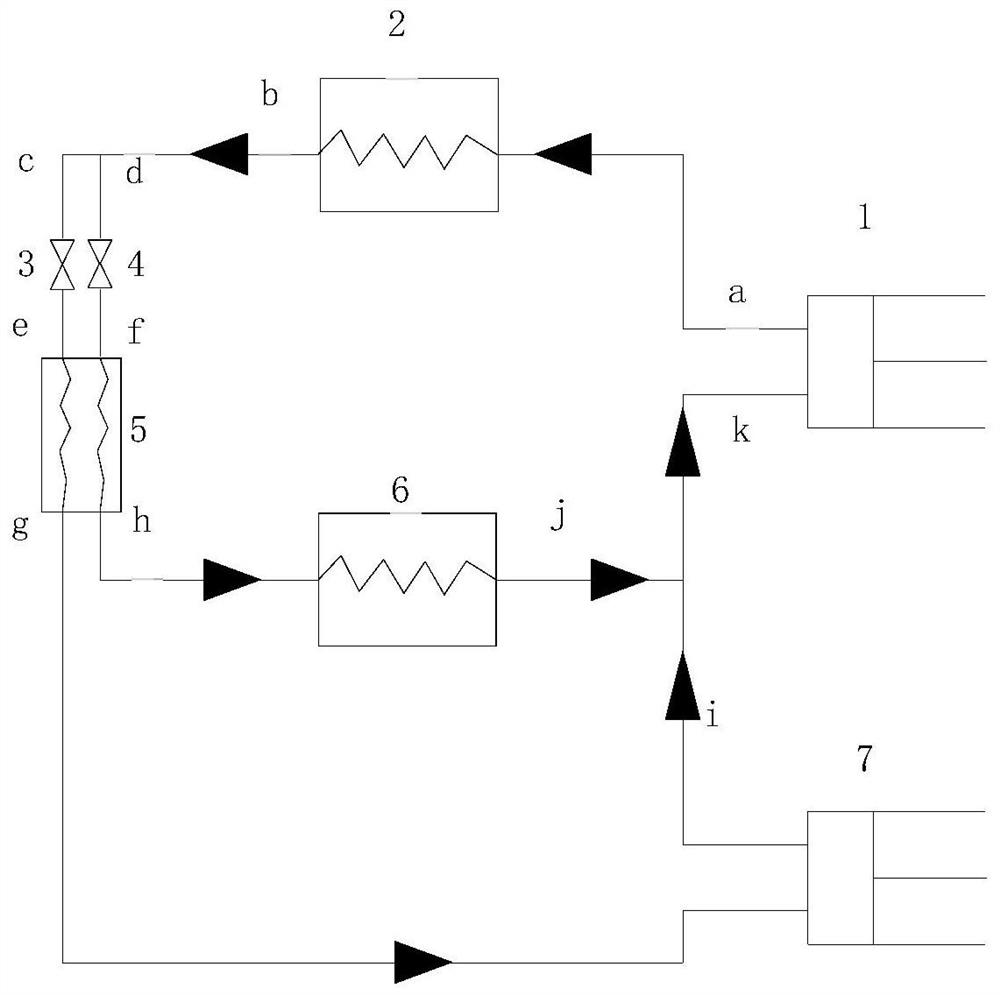
[0021] Attached below figure 1 Examples of the present invention will be described in detail, but the present invention is not limited to the following embodiments.

[0022] like figure 1 As shown, the refrigeration system using a dry evaporator according to the present invention includes a compressor 1, a condenser 2, an evaporator liquefier 5, a dry evaporator 6 and a second compressor 7, and the condenser 2 and the evaporator liquefier 5, a first throttling valve 3 and a second throttling valve 4 are arranged side by side, and the compressor 1, condenser 2, first throttling valve 3, evaporator liquefier 5, and second compressor 7 form the first throttling valve in sequence. In the first circuit, the compressor 1, condenser 2, second throttle valve 4, evaporator liquefier 5, and dry evaporator 6 sequentially form a second circuit; in the evaporator liquefier 5, the refrigeration in the first circuit The refrigerant exchanges heat with the refrigerant in the second circuit,...


PUM


Abstract

The invention discloses a refrigeration system for improving inlet refrigerant distribution uniformity of a multi-channel evaporator. A first compressor, a condenser, an evaporation liquefier, a dry evaporator and a second compressor are included. A first throttling valve and a second throttling valve are arranged between the condenser and the evaporation liquefier in parallel. A first loop is sequentially formed by the first compressor, the condenser, the first throttling valve, the evaporation liquefier and the second compressor. A second loop is sequentially formed by the first compressor,the condenser, the second throttling valve, the evaporation liquefier and the dry evaporator. In the evaporation liquefier, a refrigerant in the first loop exchanges heat with a refrigerant in the second loop; and in the evaporation liquefier, a refrigerant outlet of the first loop is connected with a second compressor inlet, and a dry evaporator outlet communicates with a first compressor suctionport after being converged with a second compressor outlet. By means of the refrigeration system, the dryness of the evaporator inlet refrigerant is reduced, and the problem about uneven distributionin the dry evaporator is solved.

Description

technical field [0001] The invention relates to the technical field of refrigeration, in particular to a refrigeration system using a dry multi-channel evaporator. Background technique [0002] The dry evaporator is a commonly used heat exchange component in the refrigeration system, and it is also an important part of the refrigeration system to output cold capacity to the outside. In the tube side of the evaporator, the refrigerant flows in the tube of the dry evaporator, absorbs the heat of the refrigerant outside the tube along the way and gradually vaporizes. Due to this structural feature, the dry-type evaporator has less refrigerant charge, stable and convenient oil return, and is widely used. In the occasions where the refrigerant charge is strictly limited, the use of dry-type evaporators is more popular. [0003] Uneven distribution of inlet refrigerant is the main problem existing in the use of existing dry evaporative coolers. The liquid-phase refrigerant at th...

Claims


Application Information

Patent Timeline
Patent Type & Authority Patents(China)
IPC IPC(8): F25B7/00F25B39/02
CPCF25B7/00F25B39/028F25B2339/02F25B2500/09
Inventor 宣永梅陈光明高能
Owner NINGBO INST OF TECH ZHEJIANG UNIV ZHEJIANG
Why Eureka
Try Eureka