
Telemetering device assembly

A remote measurement device and assembly technology, applied in the field of power grid, can solve the problems of lack of real-time performance, and achieve the effects of easy and flexible use, good monitoring effect, and cost reduction

Pending Publication Date: 2019-07-19
匠石电力电子科技(镇江)有限公司
View PDF0 Cites 1 Cited by
  • Summary
  • Abstract
  • Description
  • Claims
  • Application Information

AI Technical Summary

Problems solved by technology

Therefore, line workers need to solve this problem. Professional lenses can capture the invisible light (corona) produced when the air reacts with the electric field. The lines are often monitored through various line inspection modes, which have no real-time performance.

Method used


Image

  • Telemetering device assembly
  • Telemetering device assembly
  • Telemetering device assembly

Examples


Embodiment Construction

[0028] The present invention will be further described below in conjunction with the accompanying drawings and specific embodiments.

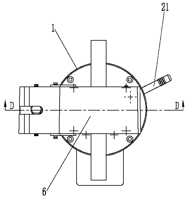
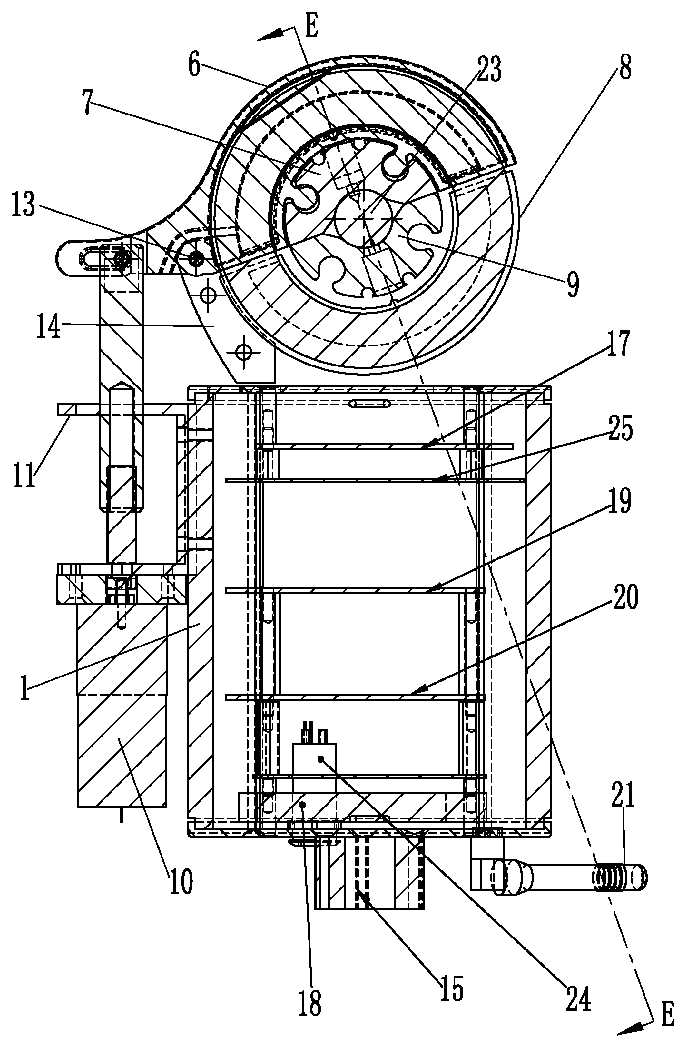
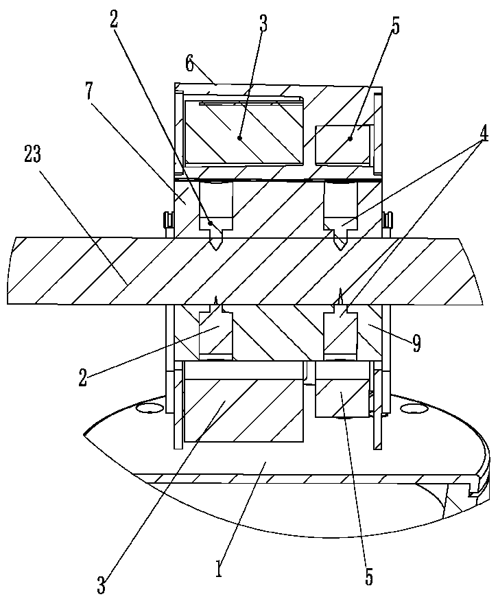
[0029] Such as Figure 1-5 As shown, a telemetry device assembly includes the following parts:

[0030] The box body 1 is made of magnetic shielding material;

[0031] The clamping mechanism installed on the box body 1 for clamping the cable 23 has a detection component for detecting the current and voltage of the conductor in the cable 23;

[0032] A sleeve 15 fixed on the box body 1 and detachably set on the copper bar 16 at the terminal of the substation power transformer during detection;

[0033] The GPRS antenna 21 that is installed on the box body 1 and communicates with the remote control platform 22; and

[0034] control unit;

[0035] Wherein, the control unit includes a power management circuit board 17, a data processing circuit board 19, a remote control circuit board 20, and a GPRS antenna 21, a remote control circuit board 20...


PUM


Abstract

The invention relates to a telemetering device assembly in the technical field of power grids. The telemetering device assembly comprises a box, a clamping mechanism, a sleeve, a GPRS antenna and a control unit, wherein the box is made of a magnetic shielding material; the clamping mechanism is mounted on the box, is used for clamping cables, and is provided with a detection assembly for detectingthe current and voltage of conductors in the cables; the sleeve is fixed on the box and can be detachably sleeved on a copper bar at the terminal of a substation power transformer during the detection; the GPRS antenna is mounted on the box and communicably connected with a remote control platform; the control unit comprises a power management circuit board, a data processing circuit board and aremote control circuit board; and the GPRS antenna, the remote control circuit board and the data processing circuit board are connected in sequence. The telemetering device assembly is capable of monitoring the current and voltage values and fault points of power grids in real time, is small in volume, and is capable of saving a large number of control cabinets so as to remarkably reduce the substation construction cost.

Description

technical field [0001] The invention relates to the technical field of power grids, in particular to a real-time measurement system applied in power grids. Background technique [0002] Electricity enters the high-voltage and ultra-high-voltage transmission network from the generator through the step-up transformer until the distribution network (real-time measurement of electric power along this line is impossible, and can only be completed through voltage and current transformers at the substation). Inside a high-voltage transmission line, hundreds of thousands of volts create a huge electric field that radiates outward from around the line. This electric field is very strong and can reach the ground directly. If there is a leakage on the wire, the electric field will become extremely strong, electrifying the surrounding air, and causing corona discharge. The stronger the invisible corona, the more severe the high-voltage leakage will be. If it is not stopped, there wil...

Claims


Application Information

Patent Timeline
IPC IPC(8): G01R31/08G01R19/00
CPCG01R31/086G01R19/00
Inventor 纪圣谋蒋浩鑫
Owner 匠石电力电子科技(镇江)有限公司
Learn More