Dampproof connector of computer power line

A computer power supply and electrical connection technology, which is applied in the computer field, can solve the problems that the power cord joints are easily affected by moisture, and achieve the effect of promoting drainage, improving bending resistance, and reducing content

Active Publication Date: 2019-07-19
九州阳光电源(深圳)有限公司
View PDF27 Cites 0 Cited by
  • Summary
  • Abstract
  • Description
  • Claims
  • Application Information

AI Technical Summary

Problems solved by technology

[0005] The purpose of the present invention is to provide a moisture-proof connector for computer power cords that can automaticall

Method used


Image

  • Dampproof connector of computer power line
  • Dampproof connector of computer power line
  • Dampproof connector of computer power line

Examples


Embodiment 1

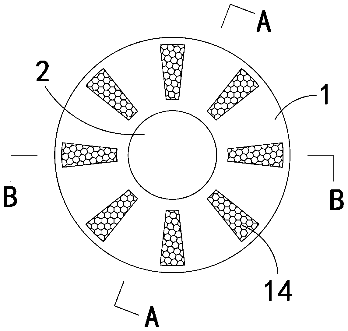
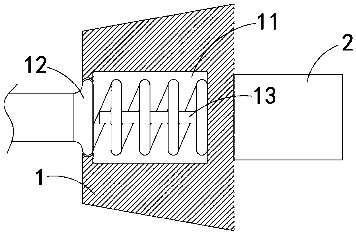
[0031] Such as Figure 1-3 As shown, a moisture-proof connector for a computer power cord includes a holding head 1 and a plug 2, the plug 2 is fixedly connected to the front side wall of the holding head 1, the plug 2 matches the jack of the computer power supply, and the holding head 1 includes :

[0032] A cavity 11, the cavity 11 is arranged in the holding head 1, and the rear side of the cavity 11 communicates with the outside;

[0033] A spiral wire 12, one end of the spiral wire 12 is fixedly connected to the side wall of the cavity 11 and electrically connected to the plug 2, and the other end of the spiral wire 12 extends outside the holding head 1 and is connected to an external power supply;

[0034] The heat conduction rod 13, the heat conduction rod 13 is located in the spiral wire 12 and coaxially arranged with the spiral wire 12, one end of the heat conduction rod 13 is fixedly connected with the side wall of the cavity 11, the heat conduction rod 13 can be mad...

Embodiment 2

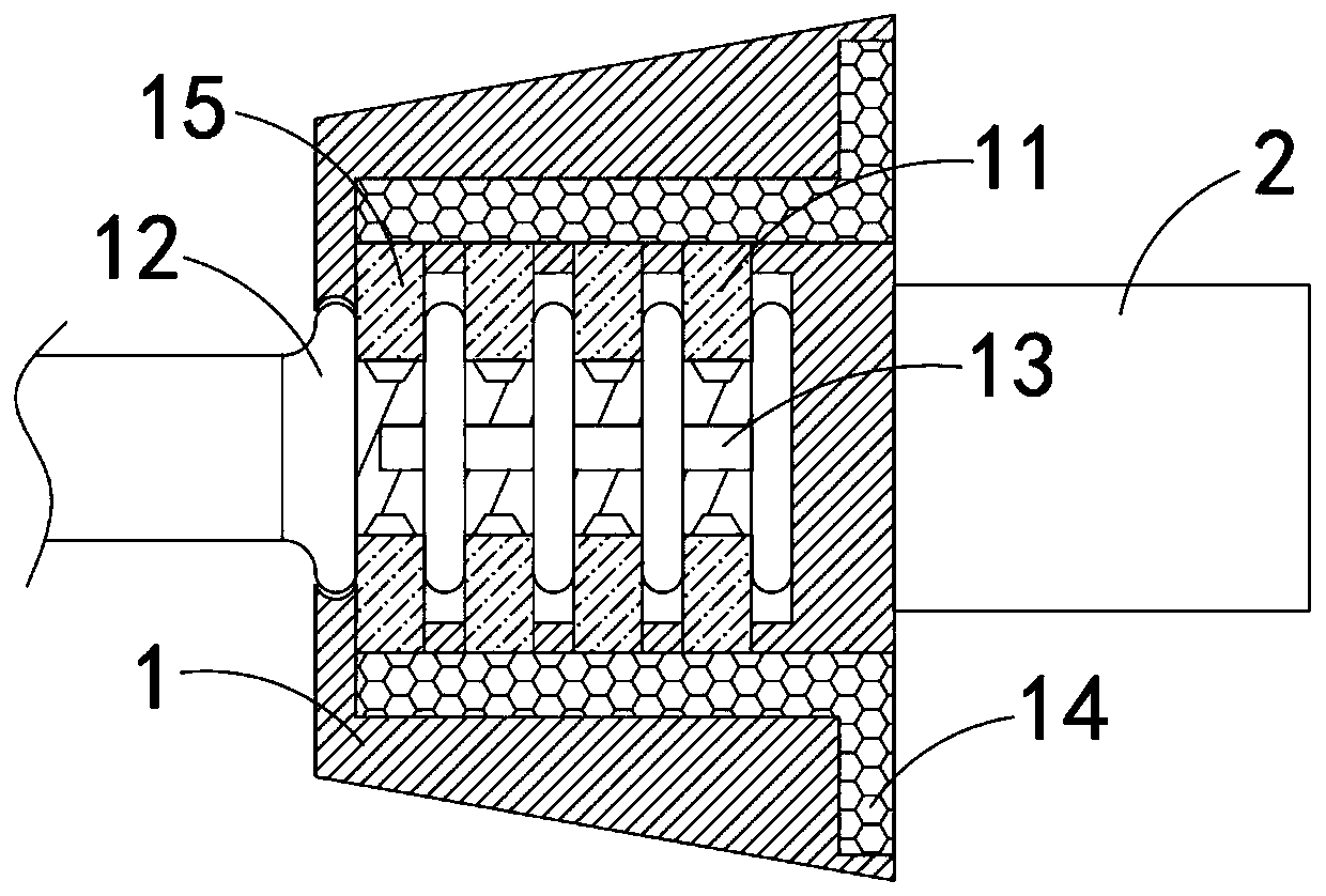
[0039] Such as Figure 4-5 As shown, the difference between this embodiment and Embodiment 1 is that an annular groove is provided in the gripping head 1, and an annular airbag 16 is arranged in the annular groove, and the annular airbag 16 is made of elastic material such as silica gel. Kit features:

[0040] Elastic bellows 17, one end of the elastic bellows 17 is fixed and sealed with the side wall of the cavity 11, the elastic bellows 17 can only expand and contract freely along its axial direction, and the holding head 1 is provided with a plurality of connecting elastic bellows 17 and The channel 171 of the annular airbag 16;

[0041] Magnetic slider 18, the rear side of magnetic slider 18 is S pole, the front side is N pole, magnetic slider 18 is in sliding and sealing connection with heat conducting rod 13, and the side wall of magnetic slider 18 is in fixed and sealing connection with elastic bellows 17.

[0042] In this embodiment, after the spiral conductor 12 is ...


PUM


Abstract

The invention belongs to the field of computers, and particularly relates to a dampproof connector of a computer power line. The dampproof connector comprises a handhold head and a plug, wherein the plug is fixedly connected with a front side wall of the handhold head, the handhold head comprises a cavity, a spiral wire, a heat conduction rod, multiple water absorption strips and multiple water storage blocks, the cavity is arranged in the handhold head, a rear side of the cavity communicates with the exterior, one end of the spiral wire is fixedly connected with a side wall of the cavity andis electrically connected with the plug, the other end of the spiral wire extends to the handhold head and is connected with an external power supply, the heat conduction rod is arranged in the spiralwire, the heat conduction rod and the spiral wire are coaxially arranged, one end of the heat conduction rod is fixedly connected with the side wall of the cavity, the water absorption strip are embedded onto a front side wall of the handhold head, the multiple water absorption strips are uniformly arranged around an axis of the spiral wire, and one end of each water storage block is fixedly connected with the water absorption strip. The dampproof connector has a relatively high dampproof effect, the situation that the connector is affected with damp to get rust can be reduced, and the service lifetime of the power line is prolonged.

Description

technical field [0001] The invention belongs to the field of computers, in particular to a moisture-proof connector for computer power lines. Background technique [0002] Since the operating voltage of the core components of the computer is very low, and the operating frequency of the computer is very high, the requirements for the power supply are relatively high. At present, the power supply of the computer is a switching circuit, which converts ordinary alternating current into direct current, and then controls the voltage through chopping, and outputs different voltages to computer components such as the motherboard, hard disk, and optical drive. [0003] The computer power supply is generally connected to the external mains power supply through the power cord. During the use of the computer, because there will be a gap between the power cord plug and the computer power supply, a large amount of water vapor in the air will cause Corrosion at the joints will not only af...

Claims


Application Information

Patent Timeline
IPC IPC(8): H01R13/52H01R13/502H01R13/56B01D53/26
CPCB01D53/26B01D2257/80H01R13/502H01R13/52H01R13/5227H01R13/56H01R2201/06
Inventor 邓东
Owner 九州阳光电源(深圳)有限公司
Why Eureka
Try Eureka