Supercharge Your Innovation With Domain-Expert AI Agents!

Vacuum attachment device

A technology of vacuum adsorption and adsorption part, which is applied in the direction of suction cups, connecting components, household appliances, etc. It can solve the problems of screw damage of levers or screws, reduction of adsorption function, separation of suction cups, etc., so as to prevent the easy failure of adsorption and the occurrence of height The effect of changing, preventing loosening or deformation

Active Publication Date: 2019-07-19
林根伯
View PDF15 Cites 0 Cited by
  • Summary
  • Abstract
  • Description
  • Claims
  • Application Information

AI Technical Summary

Problems solved by technology

It can conveniently fix items on the wall, etc., but the structure used to form a vacuum is complicated, or it cannot form a complete vacuum
[0004] For example, when creating a vacuum with a lever or tightening a screw, it is difficult to grasp the sufficient tightening strength required to create a vacuum, so there is a problem that the helix of the lever or screw is worn out or that various parts such as the rotating body are damaged.
Moreover, the above-mentioned adsorption device using vacuum is composed of separate components such as a suction cup, a pressurization adjustment device, a cover, etc. After long-term use, the suction cup is separated or loosened. without breaking the vacuum
[0005] In addition, in the conventional products, when the rotation is locked, the suspension is separated from the suction device. Therefore, when placing objects, it is difficult to maintain balance due to the load acting on the suspension.
Therefore, the method of forming the hanging part on the central axis of the adsorption device is used, but the external force applied to the hanging part directly acts on the vacuum chamber of the adsorption device, and the adsorption function is reduced.

Method used


Image

  • Vacuum attachment device
  • Vacuum attachment device
  • Vacuum attachment device

Examples


Embodiment Construction

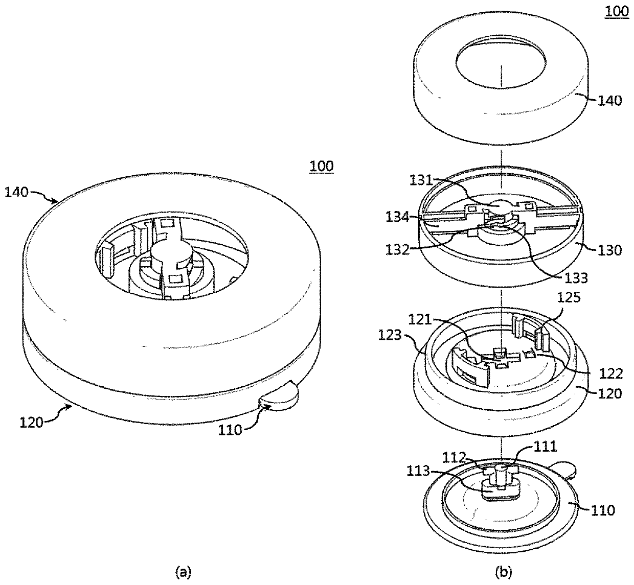
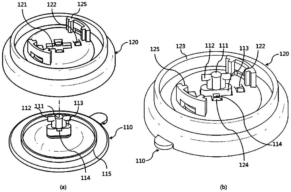
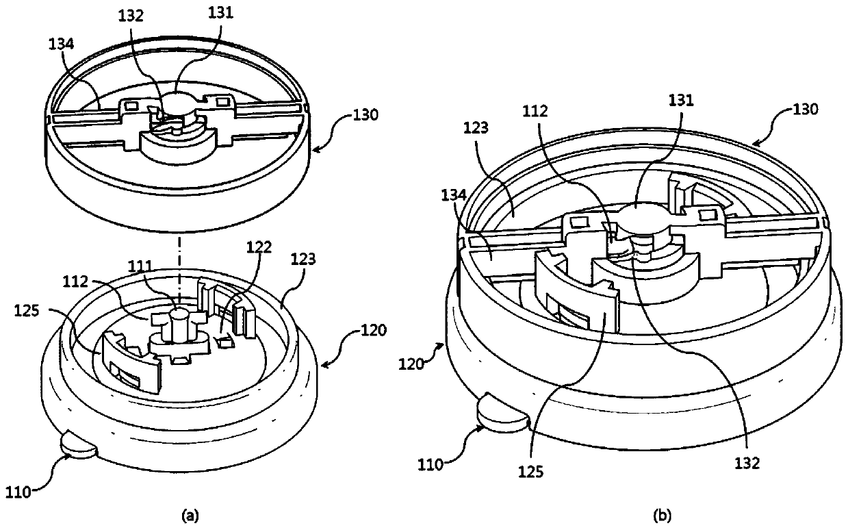
[0046] Hereinafter, embodiments of the present invention will be described with reference to the drawings. Furthermore, when attaching reference signs to constituent elements in each drawing, the same constituent elements are given the same reference numerals as much as possible even if they are shown in different drawings. Also, when describing the embodiments of the present invention, if it is judged that detailed descriptions of related known configurations or functions hinder the understanding of the embodiments of the present invention, the detailed descriptions thereof will be omitted. Moreover, although the Example of this invention is demonstrated below, the technical thought of this invention is not limited to this, Those skilled in the art can change and implement it differently.

[0047] Throughout the specification, when it is described that a certain part is "connected" to other parts, it includes not only the case of "directly connected" but also the case of "ind...


PUM


Abstract

A vacuum attachment device is provided according to an embodiment of the present invention. The vacuum attachment device comprises: an attachment portion having a vacuum chamber formed on the bottom surface thereof such that the same is vacuum-attached to an attachment target surface and having a rotation support shaft formed to protrude from the upper surface thereof; a body portion coupled to the upper side of the attachment portion, an insertion hole being formed through the body portion such that the rotation support shaft is inserted therein; and a rotation control portion arranged on theupper side of the body portion such that the same can rotate with regard to the body portion and the rotation support shaft, wherein the rotation support shaft has at least one control shaft formed to protrude outward, and the control shaft can ascend or descend following a rotation of the rotation control portion and thereby form a vacuum in the attachment portion or remove the same therefrom.

Description

technical field [0001] The present invention relates to a vacuum adsorption device, and more specifically, to a vacuum adsorption device that forms or releases a vacuum through a user's rotation action. Background technique [0002] Generally speaking, when storing and storing various items such as bathroom supplies, kitchen supplies, or simple indoor objects, other storage tools or hanging pieces are pasted on the wall or glass wool for storage and use. If it is an ordinary wall surface, it can be attached with nails, etc., but it cannot be used by the above-mentioned method on a tile or glass wall surface. [0003] Therefore, recently, an adsorption device for attaching and fixing articles to a wall surface by vacuum adsorption has been widely used. It can conveniently fix objects on the wall, etc., but the structure for forming a vacuum is complicated, or it cannot form a complete vacuum. [0004] For example, when creating a vacuum with a lever or tightening a screw, i...

Claims


Application Information

Patent Timeline
IPC IPC(8): F16B47/00
CPCF16B47/00A47K2201/02F16B47/006
Inventor 林根伯
Owner 林根伯
Features
  • R&D
  • Intellectual Property
  • Life Sciences
  • Materials
  • Tech Scout
  • Unparalleled Data Quality
  • Higher Quality Content
  • 60% Fewer Hallucinations
Learn More