Design method of steam pipe flow stabilizing device and seawater desalination system thereof

A technology of a steady flow device and a design method, which is applied in separation methods, seawater treatment, and general water supply conservation, etc., and can solve problems that restrict the development of islands, national defense, lack of fresh water, and inhabitability, so as to improve heat transfer efficiency and improve heat transfer Efficiency, the effect of maximum utilization effect

Active Publication Date: 2019-07-23
SHANDONG UNIV
View PDF6 Cites 1 Cited by
  • Summary
  • Abstract
  • Description
  • Claims
  • Application Information

AI Technical Summary

Problems solved by technology

[0004] There are more than 10,000 islands in China, but most of them are uninhabitable due to lack of fresh water, and there are less than 500 permanent residents, which restricts the development of islands, national defense and other functions

Method used


Image

  • Design method of steam pipe flow stabilizing device and seawater desalination system thereof
  • Design method of steam pipe flow stabilizing device and seawater desalination system thereof
  • Design method of steam pipe flow stabilizing device and seawater desalination system thereof

Examples


Embodiment Construction

[0071] The specific embodiments of the present invention will be described in detail below in conjunction with the accompanying drawings.

[0072] In this article, if there is no special explanation, when it comes to formulas, " / " means division, and "×" and "*" mean multiplication.

[0073] The specific embodiments of the present invention will be described in detail below in conjunction with the accompanying drawings.

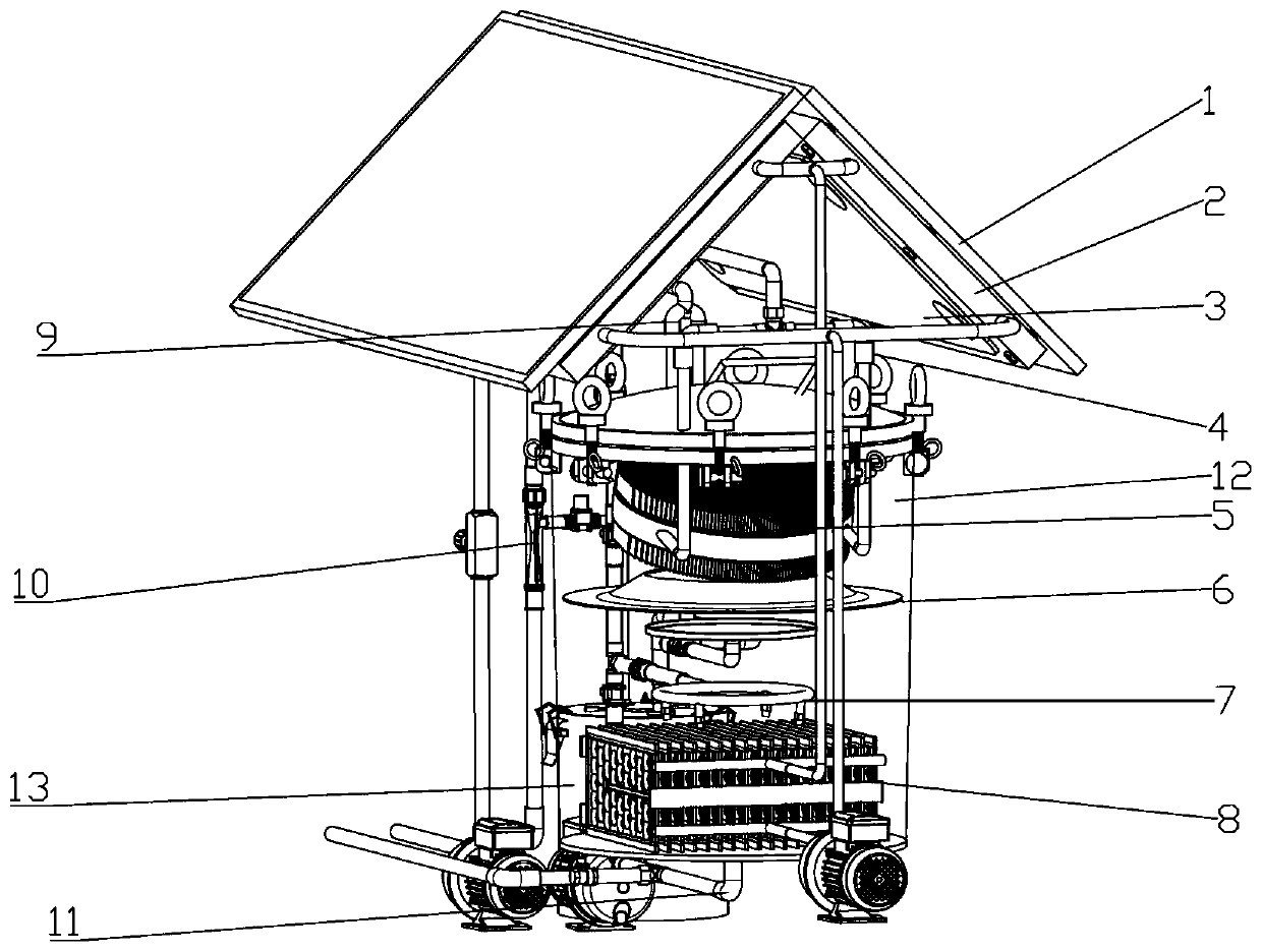
[0074] Such as figure 1 A seawater desalination system is shown. The seawater desalination system includes an evaporation system, a condensation system and a freshwater collection system. The seawater is evaporated in the evaporation system to generate steam, and then the steam is condensed in the condensation system to become fresh water, and then the fresh water is collected through the fresh water system to collect.

[0075] The evaporation system includes a solar heat collector 1 and a loop heat pipe 2, the loop heat pipe 2 absorbs solar energy at the ...


PUM


Abstract

The invention provides a design method of a steam pipe flow stabilizing device and a seawater desalinization system thereof. An evaporator comprises an inlet header, an outlet header and a heat exchange component connected between the headers, wherein the inlet header and the outlet header are respectively connected with a steam inlet pipe and a condensed water outlet pipe; flow stabilizing devices are arranged in the steam inlet pipe of the inlet header; each flow stabilizing device is a sheet-shaped structure; the sheet-shaped structure is arranged on the cross section of the steam inlet pipe, the flow stabilizing devices in the steam inlet pipe are designed in the following way: a plurality of flow stabilizing devices are arranged in the steam inlet pipe, and the closer to the inlet header, the smaller the spacing between the flow stabilizing devices is. Because the closer to the inlet header, the vibration and the noise may continue to increase, and the vibration and the noise needto be further alleviated. Therefore, the spacing between adjacent flow stabilizing devices to be arranged is getting shorter and shorter. A new design method is adopted to continuously separate a gasphase and a liquid phase in a fluid conveying process.

Description

technical field [0001] The invention relates to the field of heat exchangers, in particular to a steady flow evaporator. Background technique [0002] Heat pipe technology was developed in Los Alamos, USA in 1963. national laboratory A heat transfer method called a "heat pipe" invented by George Grover element , it makes full use of the principle of heat conduction and the rapid heat transfer properties of phase change media, and quickly transfers the heat of the heating object to the outside of the heat source through the heat pipe, and its thermal conductivity exceeds that of any known metal. [0003] Heat pipe technology was widely used in aerospace, military and other industries before. Since it was introduced into the radiator manufacturing industry, people have changed the traditional radiator design ideas and got rid of the single heat dissipation mode that only relies on high air volume motors to obtain better heat dissipation. The use of heat pipe technology enab...

Claims


Application Information

Patent Timeline
Patent Type & Authority Applications(China)
IPC IPC(8): B01D1/00C02F1/04C02F1/14C02F103/08
CPCB01D1/0011C02F1/043C02F1/14C02F2103/08C02F2301/063Y02A20/124Y02A20/142Y02A20/212
Inventor 郭春生李佳航周磊赵婉莹
Owner SHANDONG UNIV
Why Eureka
Try Eureka