
A blower expansion stamping die

A technology of flaring stamping and blower, applied in the direction of manufacturing tools, perforating tools, metal processing equipment, etc., to reduce damage, ensure production quality, and reduce labor intensity

Active Publication Date: 2020-06-23
ZHEDIAN METAL TECH SHANGHAI
View PDF7 Cites 0 Cited by
  • Summary
  • Abstract
  • Description
  • Claims
  • Application Information

AI Technical Summary

Problems solved by technology

[0006] In view of the above technical problems, the purpose of the present invention is to provide an air duct flaring stamping die. When the air duct is expanded, the side wall of the supporting column is used to press and support the air duct away from the side of the air duct to be flared. The inner wall of the hole, the inner wall of the avoidance hole is pressed against and supports the outer wall of the air duct away from the side of the air duct to be flared, thereby reducing the deformation of the connection between the air duct and the bottom plate and the middle of the air duct, and improving Improve the production quality of the blower and reduce the production of scrap blowers

Method used


Image

  • A blower expansion stamping die
  • A blower expansion stamping die
  • A blower expansion stamping die

Examples


Embodiment Construction

[0039] The present invention will be further described in detail below in conjunction with the embodiments and the accompanying drawings, but the embodiments of the present invention are not limited thereto.

[0040] Example:

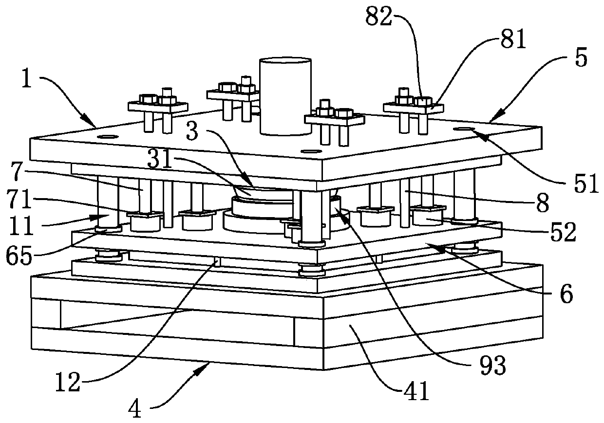
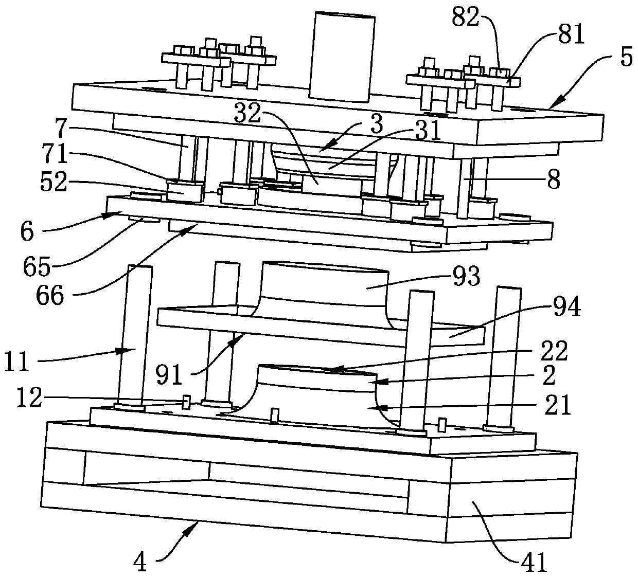
[0041] see figure 2 and image 3 , a blower flare stamping die, including a fixed template 1 and a movable template 5, a support column 2 is vertically arranged on the side of the fixed template 1 close to the movable template 5, and the connection between the support column 2 and the fixed template 1 is arranged on an arc surface And form the first abutting curved surface 21; see Figure 6 The side of the movable formwork 5 close to the fixed formwork 1 is provided with a pressing plate 6, and the surrounding edges of the side of the pressing plate 6 close to the fixed formwork 1 are all provided with avoidance step grooves 66 for embedding the air duct installation edge 94, The pressure plate 6 is provided with an avoidance hole 61, and an inner w...


PUM


Abstract

The invention discloses an air cylinder flaring punching die, and relates to the technical field of air cylinder flaring. The air cylinder flaring punching die comprises a fixed die plate and a movable die plate, wherein a supporting column is vertically arranged on one side, close to the movable die plate, of the fixed die plate, and the joint of the supporting column and the fixed die plate is in an arc curved surface to form a first abutting curved surface; a pressing plate is arranged on one side, close to the fixed die plate, of the movable die plate, an avoiding hole is formed in the pressing plate, an abutting inner wall is formed in the avoiding hole, the connecting part of the abutting inner wall and one side, close to the fixed die plate, of the abutting inner wall is provided with an arc curved surface, and a second abutting curved surface is formed; the pressing plate is arranged on the movable die plate in a sliding mode, the pressing plate slides axially along the supporting column, a driving part is further arranged on the movable die plate, a flaring head is further arranged on one side, close to the fixed die plate, of the movable die plate, and the flaring head isin a frustum shape. The air cylinder flaring punching die has the advantages that the connection position of the air guide pipe and the bottom plate and the deformation of the middle of the air guidepipe can be reduced, the production quality of an air cylinder is improved, and the generation amount of the scrapped air cylinder is reduced.

Description

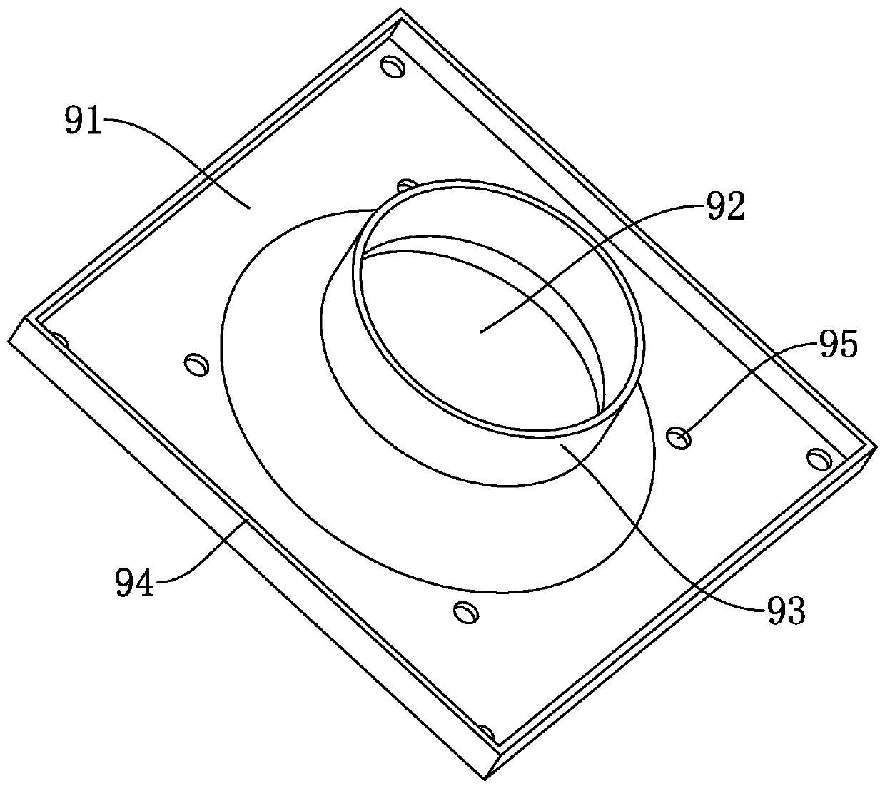
technical field [0001] The invention relates to the technical field of air cylinder flaring, in particular to an air cylinder flaring stamping die. Background technique [0002] A flaring tool is a tool that expands the opening of a hollow part or a tubular part outward. Stamping flaring dies are one of them. Stamping flaring dies are often used for flaring tubular parts , so that the tubular parts meet the requirements that the design needs to achieve. [0003] In the prior art, after the stamping flaring die passes through one end of the tubular piece of the clamping device, the other end of the tubular piece is squeezed through the flaring head, so that the opening of the tubular piece is enlarged by the flared end, and the purpose of flaring is achieved. . [0004] Referring to the accompanying drawings, there is an existing air duct, which is made of metal and includes a base plate 91. The base plate 91 is provided with a ventilation hole 92. One side of the base plat...

Claims


Application Information

Patent Timeline
Patent Type & Authority Patents(China)
IPC IPC(8): B21D41/02B21D28/34
CPCB21D28/34B21D41/02
Inventor 魏庆明张怿林胡久亮王斌
Owner ZHEDIAN METAL TECH SHANGHAI
Learn More