Concrete test block demolding device
A technology of concrete test blocks and demoulding devices, which is applied in the direction of unloading devices, manufacturing tools, etc., and can solve the problems of low demoulding efficiency, time-consuming and laborious, and low work efficiency
- Summary
- Abstract
- Description
- Claims
- Application Information
AI Technical Summary
Problems solved by technology
Method used
Image
Examples
Embodiment 1
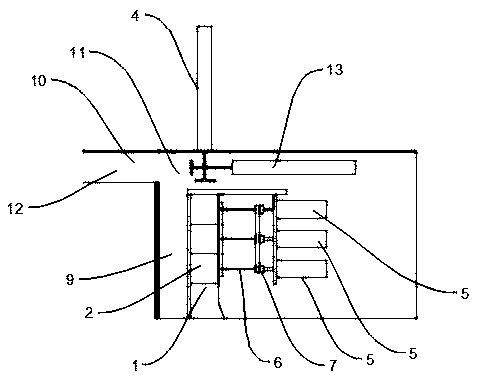
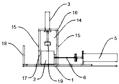
[0028] Such as figure 1 - Figure 5As shown, the present embodiment provides a demoulding device for a concrete test block, including a test form position 1 for defining the position of the concrete test form 2, a positioning push-out mechanism for positioning and pushing out the concrete test form 2, and a The driving mechanism that pushes the concrete test block out of the concrete test mold 2, the positioning push-out mechanism includes the upper driving cylinder 3 located above the concrete test mold 2 for compacting the concrete test mold 2 from the vertical direction and the side of the concrete test mold 2 The side drive cylinder 4 is used to push the concrete test mold 2 out from the entrance of the test mold position 1; the driving mechanism includes a thrust cylinder 5 that is consistent with the number of concrete test blocks and a thrust cylinder that directly applies thrust to the concrete test block through the thrust cylinder 5 The thimble assembly, the thimbl...
Embodiment 2
[0032] This embodiment is optimized and defined on the basis of the above-mentioned embodiment 1.
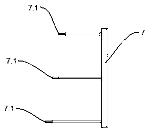
[0033] In order to realize the parallel connection of the thimbles 6, the thimbles 6 are arranged side by side on the connecting plate 7, the connecting plate 7 is fixedly connected with the piston rod of the thrust cylinder 5, and the piston rod of the thrust cylinder 5 is coaxial with the corresponding thimble 6.
Embodiment 3
[0035] This embodiment is optimized and defined on the basis of the above-mentioned embodiment 1.
[0036] Such as Image 6 As shown, in order to realize the side-by-side connection of the thimbles 6, the connecting end of the thimble 6 is fixedly connected with the piston rod of the thrust cylinder 5, and the thimble 6 is fixedly connected with the connecting plate 7 in turn.
PUM
 Abstract
Description
Claims
Application Information
 - R&D
- Intellectual Property
- Life Sciences
- Materials
- Tech Scout
- Unparalleled Data Quality
- Higher Quality Content
- 60% Fewer Hallucinations
Browse by: Latest US Patents, China's latest patents, Technical Efficacy Thesaurus, Application Domain, Technology Topic, Popular Technical Reports.
© 2025 PatSnap. All rights reserved.Legal|Privacy policy|Modern Slavery Act Transparency Statement|Sitemap|About US| Contact US: help@patsnap.com


