
Spraying gun assembly and spraying robot

A technology for spraying robots and spray guns, applied in manipulators, manufacturing tools, buildings, etc., can solve the problems of difficult to guarantee spraying accuracy, large equipment occupied space, low spraying accuracy, etc., to reduce the possibility of collision and damage, reduce The effect of small space occupation and efficient use of space

Active Publication Date: 2019-07-23
GUANGDONG BOZHILIN ROBOT CO LTD
View PDF11 Cites 5 Cited by
  • Summary
  • Abstract
  • Description
  • Claims
  • Application Information

AI Technical Summary

Problems solved by technology

[0002] At present, in the construction and decoration industry, manual spraying is mostly used for wall spraying, which has low work efficiency and poor spraying accuracy. Some semi-automatic spraying equipment is provided on the market. Due to the limitations of the height of the equipment and its own size, the spraying range is limited and it is difficult. It is suitable for working surfaces with special shapes or complex structures, especially for working surfaces such as bay windows, wall corners, and special-shaped ceilings, where the spraying accuracy is difficult to guarantee
In addition, limited to the size of the equipment, the existing semi-automatic spraying equipment is difficult to adapt to the work requirements in different scenarios, especially not conducive to the situation where the spraying equipment needs to enter a small space
Therefore, the existing semi-automatic spraying equipment still has the problems of large space occupation, limited spraying range, low spraying precision, strong dependence on labor and high spraying cost.

Method used


Image

  • Spraying gun assembly and spraying robot
  • Spraying gun assembly and spraying robot
  • Spraying gun assembly and spraying robot

Examples


Embodiment Construction

[0052] In order to understand the above-mentioned purpose, features and advantages of the present invention more clearly, the present invention will be further described in detail below in conjunction with the accompanying drawings and specific embodiments. It should be noted that, in the case of no conflict, the embodiments of the present application and the features in the embodiments can be combined with each other.

[0053] In the following description, many specific details are set forth in order to fully understand the present invention. However, the present invention can also be implemented in other ways different from those described here. Therefore, the protection scope of the present invention is not limited by the specific details disclosed below. EXAMPLE LIMITATIONS.

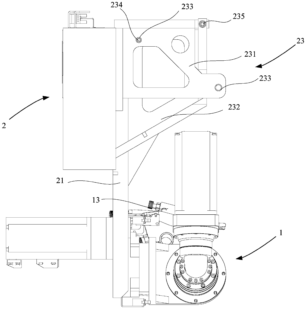
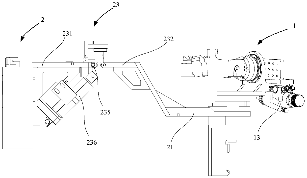
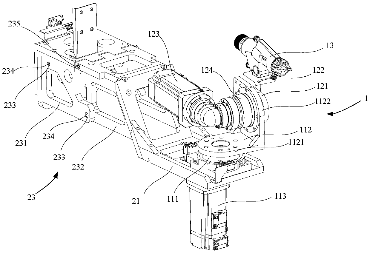
[0054] Refer below Figure 1 to Figure 7 A spray gun assembly and a painting robot according to some embodiments of the invention are described.

[0055] Such as figure 1 As shown, one embodiment ...


PUM


Abstract

The invention provides a spraying gun assembly and a spraying robot. The spraying gun assembly is used for the spraying robot including a frame, and comprises a rotating bracket, a rotating assembly and a spraying gun, wherein the rotating bracket comprises a fixed part and an extension part which are rotatably connected with each other, and the fixed part is connected with the frame; the rotatingassembly is arranged at the end, away from the fixed part, of the extension part; and the spraying gun is arranged on the rotating assembly to achieve rotation under driving of the rotating assembly,wherein when the extension part moves to the first position around a rotating shaft of the rotating bracket, the rotating assembly is close to the frame. According to the technical scheme, the scopeof spraying operation can be effectively expanded, the flexibility of spraying operation and the adaptability to the operation environment are enhanced, the dependence on labor is lowered, the accuracy of spraying is improved, the cost is lowered, and meanwhile, the volume of the spraying robot can further be decreased under the storage state, the space occupancy is reduced, and the possibility ofdamage caused by collision between the spraying assembly and external objects is reduced.

Description

technical field [0001] The invention relates to the technical field of spraying, in particular to a spray gun assembly and a spraying robot. Background technique [0002] At present, in the construction and decoration industry, manual spraying is mostly used for wall spraying, which has low work efficiency and poor spraying accuracy. Some semi-automatic spraying equipment is provided on the market. Due to the limitations of the height of the equipment and its own size, the spraying range is limited and it is difficult. It is suitable for working surfaces with special-shaped or complex structures, especially for working surfaces such as bay windows, wall corners, and special-shaped ceilings, where the spraying accuracy is difficult to guarantee. In addition, limited to the size of the equipment, the existing semi-automatic spraying equipment is difficult to adapt to the work requirements in different scenarios, especially not conducive to the situation where the spraying equi...

Claims


Application Information

Patent Timeline
IPC IPC(8): E04F21/08B25J11/00
CPCB25J11/0075E04F21/08
Inventor 刘国虬许安鹏季瑞南殷奇
Owner GUANGDONG BOZHILIN ROBOT CO LTD
Learn More