

Small car parking robot
A technology for small cars and robots, applied in the field of parking robots, can solve the problems of high cost, high robot body height, and inability to be widely used on a large scale, and achieve the effect of small structure and low cost.
- Summary
- Abstract
- Description
- Claims
- Application Information
AI Technical Summary
Problems solved by technology
Method used
Image

Examples
Embodiment 1
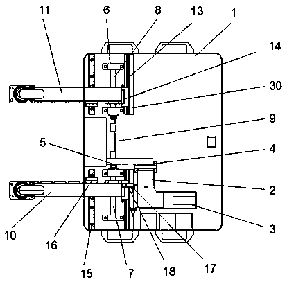
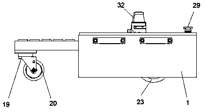
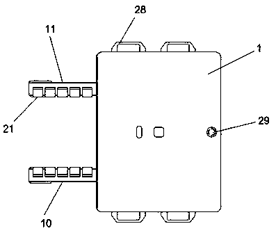
[0023] Embodiment one, such as Figure 1 to Figure 6 As shown, a small car parking robot includes a base body 1, a first clamping rod 10 and a second clamping rod 11, the base body 1 is provided with a driving reduction motor 2 inside, and the driving reduction motor 2 is fixedly installed on the In the base body 1, the output shaft of the driving reduction motor 2 is fixedly connected with the driving sprocket 4, and the driving sprocket 4 is connected with the driven sprocket 5 through a chain transmission; the base body 1 is provided with a first lead screw 7 and a second lead screw 8 , the pitch of the first lead screw 7 and the second lead screw 8 are the same and the direction of rotation is opposite. Both ends of the first lead screw 7 and the second lead screw 8 are connected with bearing mounts 6 through bearings, and the bearing mounts 6 are fixedly installed on the base 1, the driven sprocket 5 is fixedly connected with the first lead screw 7 through a key, and the ...
Embodiment 2
[0025] Embodiment 2, based on the further improvement of Embodiment 1, the base body 1 is fixedly connected with the first guide rail 13 through the mounting plate 30, and one end of the first clamping rod 10 and the second clamping rod 11 respectively pass through the first transition connecting plate 14 It is movably connected with the first guide rail 13; the middle of the first clamping rod 10 and the second clamping rod 11 is fixedly connected with the second transition connecting plate 16, and the second transition connecting plate 16 is slidably connected with the second guide rail 15 through the slider, The second guide rail 15 is fixedly connected in the base body 1 . Thus when the first clamping rod 10 and the second clamping rod 11 move on the surface of the first leading screw 7 and the second leading screw 8 through the lead screw nut 12 respectively, the first clamping rod 10 and the second clamping rod 11 The end faces of the first transition connecting plate 14...
Embodiment 3
[0026] Embodiment 3, based on a further improvement of Embodiment 1, a detection switch 17 is fixedly installed on the mounting plate 30 , a detection device 18 is fixedly connected to the first clamping rod 10 , and the detection device 18 is electrically connected to the detection switch 17 . Whether the first clamping rod 10 is clamped in place can be detected by the detection device 18, and since the first clamping rod 10 and the second clamping rod 11 are synchronous, a detection device 18 can be installed to check the first clamping rod. 10 and the second clamping rod 11 for detection.
PUM
 Abstract
Description
Claims
Application Information