Supercharge Your Innovation With Domain-Expert AI Agents!

Automatic antenna position adjustment device and method

An antenna position and automatic adjustment technology, applied in the field of rail transit, can solve the problems of poor manual adjustment accuracy, difficult antenna position calibration, and long adjustment time, so as to improve adjustment accuracy, avoid difficult calibration, and reduce adjustment time. Effect

Pending Publication Date: 2019-07-23
SHANGHAI ELECTRIC THALES TRANSPORTATION AUTOMATION SYST CO LTD
View PDF0 Cites 2 Cited by
  • Summary
  • Abstract
  • Description
  • Claims
  • Application Information

AI Technical Summary

Problems solved by technology

[0003] The purpose of the present invention is to provide an automatic antenna position adjustment device and adjustment method, which solves the problems of poor manual adjustment accuracy, long adjustment time, low efficiency, and difficult calibration of the antenna position after long-term use

Method used


Image

  • Automatic antenna position adjustment device and method
  • Automatic antenna position adjustment device and method
  • Automatic antenna position adjustment device and method

Examples


Embodiment Construction

[0023] The present invention will be further described below in conjunction with accompanying drawing.

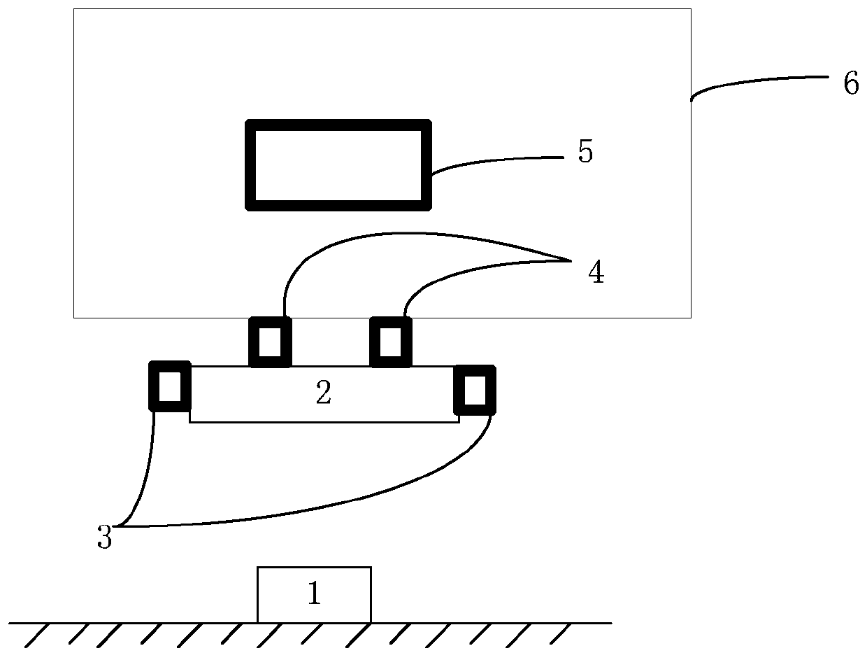
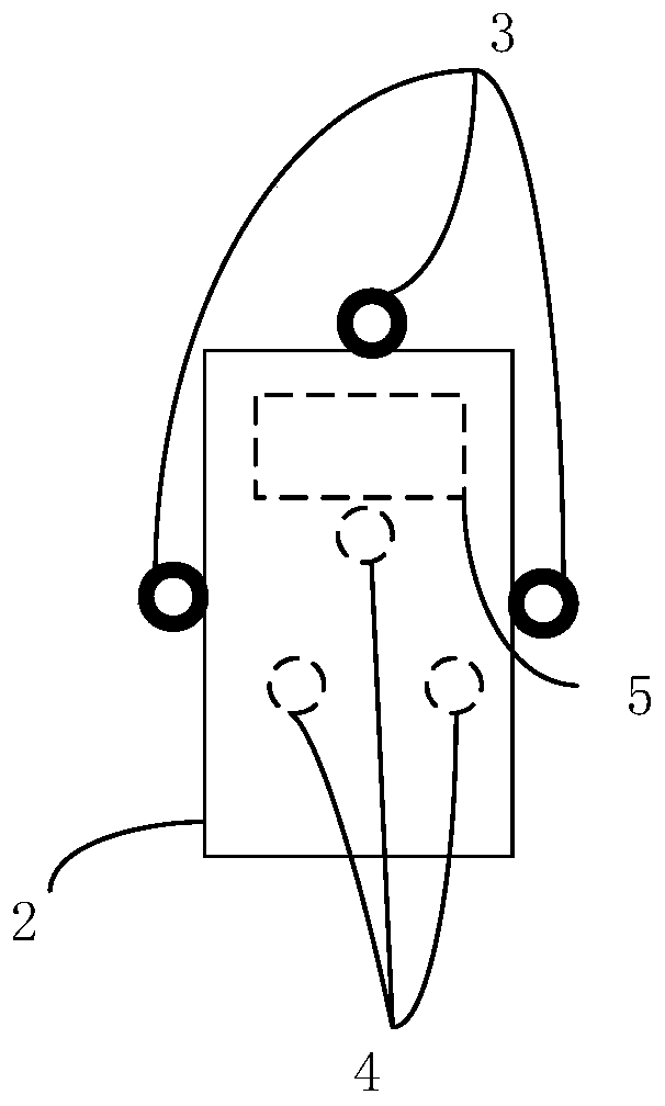
[0024] see Figure 1-2 , The antenna position automatic adjustment device of the present invention includes: an antenna 2 , at least three position measurement units 3 , a position adjustment unit 4 and a position control unit 5 .

[0025] Each position measurement unit 3 is fixed on the side of the antenna 2, and is used to measure the position data of the antenna 2 relative to the beacon 1 in the orbit, that is, the coordinates of each point in the coordinate system. The positions described below refer to the coordinates of each point similarly.

[0026] Set the coordinate system: set the direction parallel to the track as the X direction; according to the Cartesian coordinate system, the direction parallel to the ground plane of the track and perpendicular to the X direction is the Y direction; the direction perpendicular to the plane composed of the X direction and the ...


PUM


Abstract

The invention discloses an automatic antenna position adjustment device comprising an antenna, at least three position measurement units, a position control unit and a position adjustment unit; at least three position measurement units are fixed on the side surface of the antenna, for measuring the position data of the antenna with respect to a beacon in a pathway; the position control unit inputseach piece of position data into a plane fitting equation for fitting a plane of the current position of the antenna, also inputs the preset best position of the antenna with respect to the beacon into the plane fitting equation for fitting a plane of the best position of the antenna, and sends the difference between the plane of the current position of the antenna and the plane of the best position of the antenna to the position adjustment unit; the position adjustment unit adjusts the position of the antenna according to the difference. The invention also discloses an automatic antenna position adjustment method. The problems that the manual adjustment is poor in accuracy, long in adjustment time and low in efficiency, and after long time use, the position of the antenna is relatively difficult to adjust are solved.

Description

technical field [0001] The invention relates to the technical field of rail transit, in particular to an antenna position automatic adjustment device and method. Background technique [0002] At present, in the field of rail transit, the adjustment of the antenna position is achieved by manual adjustment combined with observation of the level to achieve the best position. Such an adjustment method not only has poor accuracy, but also takes a long time to adjust and has low efficiency, and it is difficult to calibrate the antenna position after a long period of use. Contents of the invention [0003] The purpose of the present invention is to provide an automatic antenna position adjustment device and adjustment method, which solves the problems of poor manual adjustment accuracy, long adjustment time, low efficiency, and difficult calibration of the antenna position after long-term use. [0004] The technical scheme for realizing the above-mentioned purpose is: [0005] ...

Claims


Application Information

Patent Timeline
IPC IPC(8): G05D3/00
CPCG05D3/00
Inventor 王兴海邬利挺
Owner SHANGHAI ELECTRIC THALES TRANSPORTATION AUTOMATION SYST CO LTD
Features
  • R&D
  • Intellectual Property
  • Life Sciences
  • Materials
  • Tech Scout
  • Unparalleled Data Quality
  • Higher Quality Content
  • 60% Fewer Hallucinations
Learn More