"Closed Loop" Economy of Motion Machine

Inactive Publication Date: 2010-09-09
MCGAHEE VINCENT DEPAUL
View PDF24 Cites 23 Cited by
  • Summary
  • Abstract
  • Description
  • Claims
  • Application Information

AI Technical Summary

Benefits of technology

[0010]The principle objective of the present invention is to provide a closed loop system for the apparatus depicted in FIG. 1 of U.S. Pat. No. 7,434,396, which is used for producing power from the effective buoyancy of a constrained object immersed in a liquid to produce energy with

Problems solved by technology

These devices require a steady source of flowing water, thus are very inefficient, since potential energy is lost as water flows past the paddles or turbines vanes b

Method used


Image

  • "Closed Loop" Economy of Motion Machine
  • "Closed Loop" Economy of Motion Machine
  • "Closed Loop" Economy of Motion Machine

Examples


Embodiment Construction

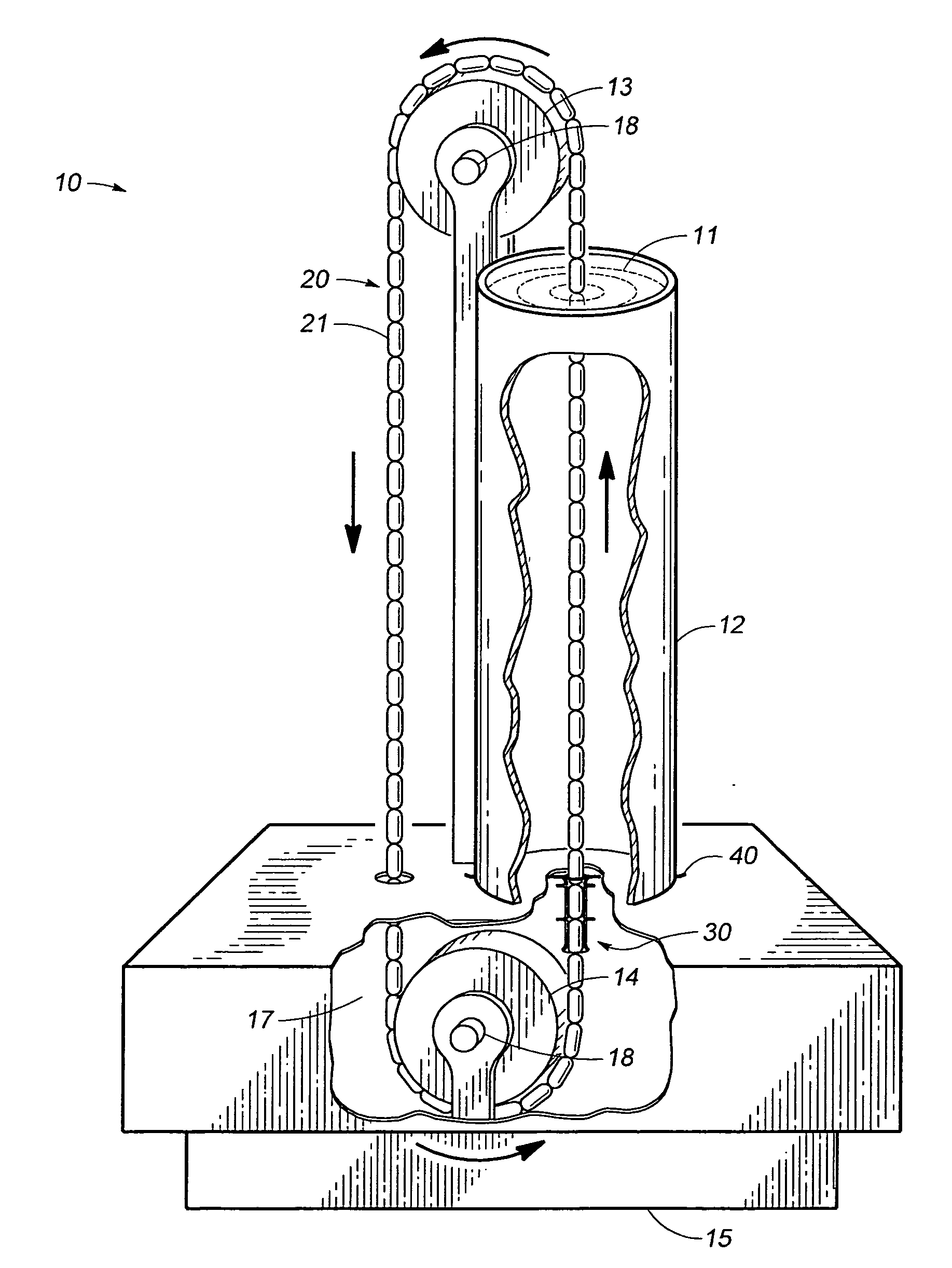
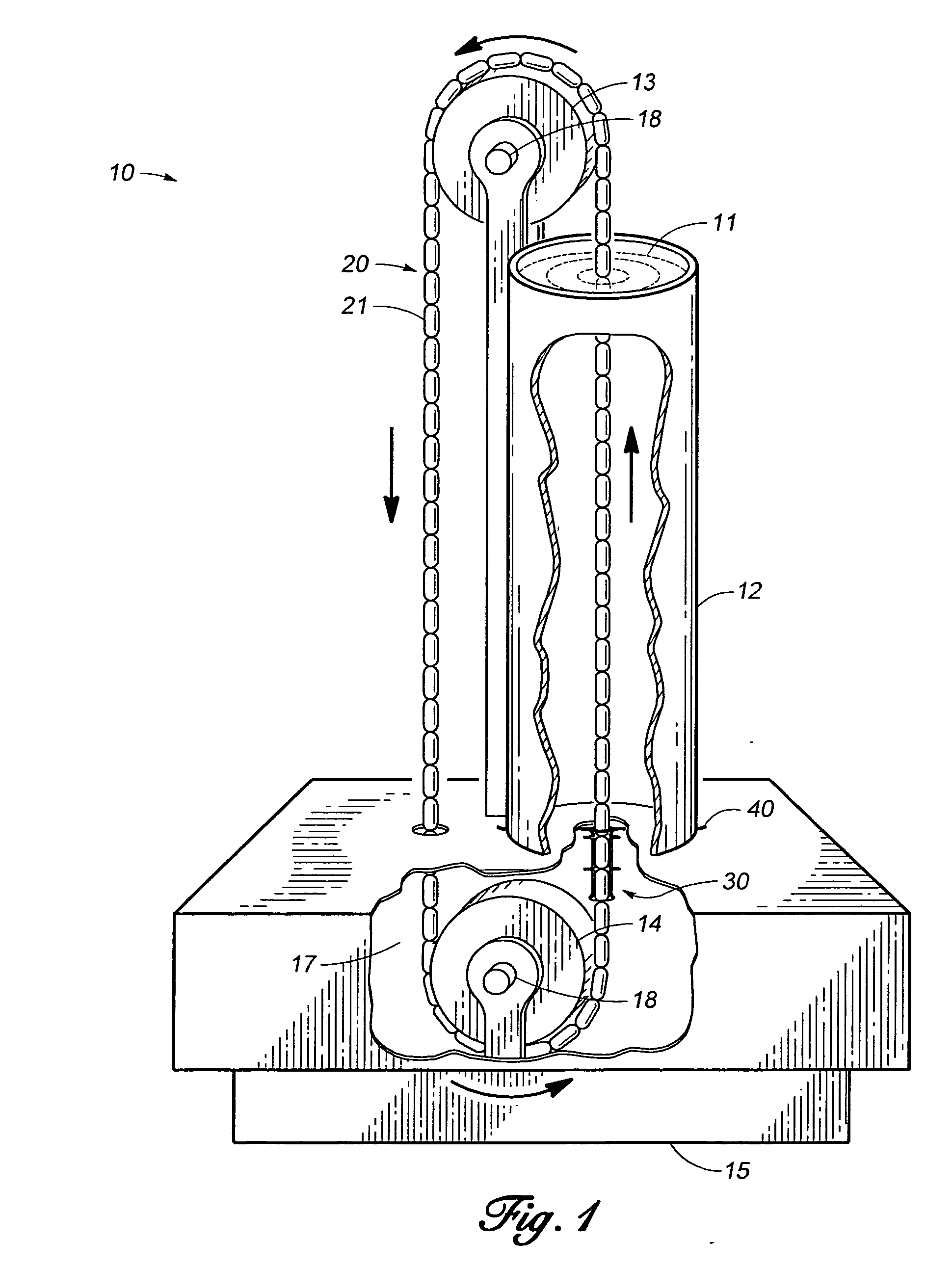
[0048]Referring more particularly to the drawings wherein similar reference characters designate like parts throughout the several reviews. FIG. 1, FIG. 2, FIG. 3, and FIG. 4 are provided for the purpose of cross referencing changes made to the parent patent and all reference characters shown in FIG. 1, FIG. 2, FIG. 3, and FIG. 4 are likewise used in all other associated drawings of the preferred embodiment.

[0049]The “Closed Loop” Economy of Motion Machine, 10a of FIG. 5, allows the displacing elements 21 forming the displacement chain 20 to move up through the liquid column 11 as a function of the combined buoyancy of the immersed displacing elements. Referring to FIGS. 5A-5D, during this process the total volume of displacement of liquid in the displaced liquid containment tank 12 remains constant. The displacing elements 21 travel upward in the liquid column 11 through a series of gap clearance modulators 99a-99e. As the displacing elements 21 in the chain 20 near the top of the ...


PUM


Abstract

A means and apparatus for fluid containment providing for closed loop operation of an apparatus within a column of liquid. The apparatus extracts power from a buoyant source within the contained column of liquid and is comprised of an endless chain of movable buoyant objects, a means to convert the movement of the chain into useful work and a tank filled with a constant volume column of liquid. The buoyant objects comprising the chain sequentially enter the bottom of the liquid column through an airlock seal of the current invention, move up through the column and emerge at the surface. The emerging buoyant objects leave the tank and are directed to the tank bottom where each buoyant object repeats the cycle. As the chain of buoyant objects cycles through the displaced column of liquid, the volume of liquid remains constant, with one buoyant object of the chain entering the bottom of the liquid column as one is exiting at the top surface. The invention provides for closed loop operation of the apparatus and increased control fluid flow rates within the apparatus to addresses liquid leakage due to mechanical wear at seals and to provide a controlled method for removal of friction generated heat within the apparatus. Chambered sections within the apparatus create fluid flow restriction zones where differential pressure can be controlled to further reduce the force requirement for injecting each buoyant object (a.k.a. displacing element) into the bottom of the contained column of liquid.

Description

CROSS-REFERENCE TO RELATED APPLICATIONS[0001]Not applicable.STATEMENT REGARDING FEDERALLY SPONSORED RESEARCH OR DEVELOPMENT[0002]Not applicable.NAMES OF PARTIES TO A JOINT RESEARCH AGREEMENT[0003]Not applicable.REFERENCE TO A “SEQUENCE LISTING”[0004]Not applicable.BACKGROUND OF THE INVENTION[0005](1) Field of the Invention[0006]The invention relates to a method and apparatus for producing energy without creating pollution or using any known consumables currently employed to produce energy. It is an advancement of the art for extracting energy as a function of the relative density between an object and a working fluid as described in the parent U.S. Pat. No. 7,434,396.[0007](2) Discussion of the Relevant Art[0008]Water has always been used by man for centuries to generate useful work and create energy. This has always been accomplished as a function of gravity induced motion of the water. The earliest known devices were water wheels which have evolved into modern hydroelectric system...

Claims


Application Information

Patent Timeline
IPC IPC(8): F03B17/02
CPCY02E10/20F03B17/04
Inventor MCGAHEE, WELBOURNE D.
Owner MCGAHEE VINCENT DEPAUL
Why Eureka
Try Eureka