
Safety controller applied to circuit overload protection

A safety controller and overload protection technology, applied in the field of circuits, can solve problems such as the failure of the protection switch to work normally, the bouncing fatigue of the bimetal strip, etc.

Active Publication Date: 2019-07-23
WENLING SHENLONG ELECTROMECHANICAL
View PDF9 Cites 3 Cited by
  • Summary
  • Abstract
  • Description
  • Claims
  • Application Information

AI Technical Summary

Problems solved by technology

[0002] The protection switch is a safety device connected in the circuit. It is mainly used to disconnect the circuit when abnormal faults such as overload and short circuit occur in the circuit, so as to avoid damage to the circuit or corresponding electrical equipment. At present, the commonly used protection switches are generally based on bimetallic strips. It is deformed by heat and finally separates the dynamic and static contacts to achieve the purpose of disconnecting the circuit, but the elastic recovery of the bimetal is limited. After exceeding the elastic recovery limit, it is likely to cause the bimetal to bounce fatigue, or due to abnormal current The resulting contact fusing and adhesion lead to the failure of the protection switch to work normally. For this reason, the inventor designed a protection switch using a melt fusing protection circuit. When the circuit does not have an abnormal fault, the user can manually open / close the protection switch , In the event of an abnormal fault in the circuit, it can automatically replace its own internal melt, and automatically turn off the protection switch, effectively preventing damage to the circuit and corresponding electrical equipment, and has better safety performance

Method used


Image

  • Safety controller applied to circuit overload protection
  • Safety controller applied to circuit overload protection
  • Safety controller applied to circuit overload protection

Examples


Embodiment Construction

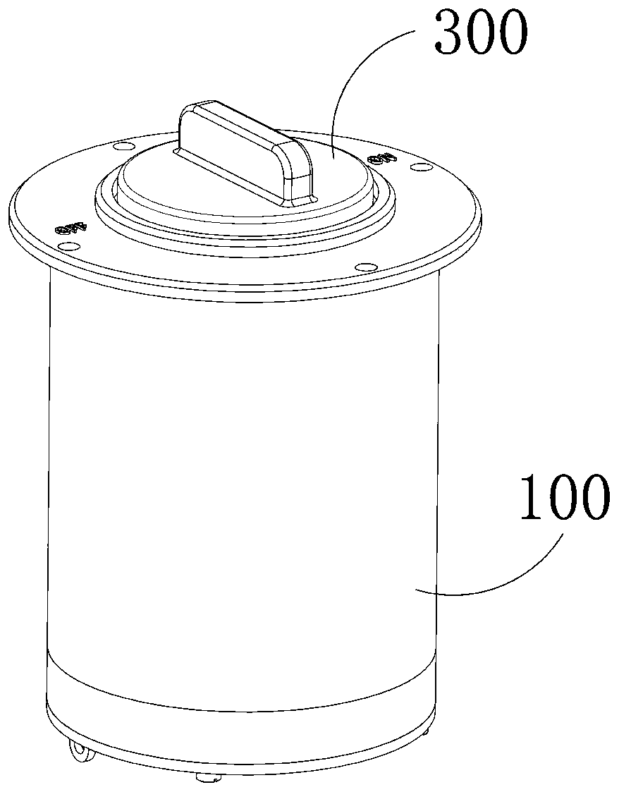
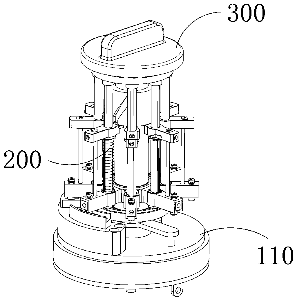
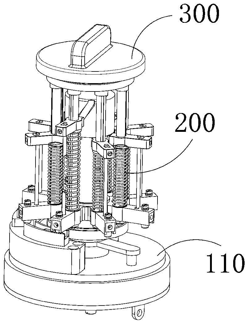
[0070] The advantage of using the circuit protection device and the knob reset device to cooperate with the opening and closing of the corresponding electrical equipment in the present invention is that when the circuit does not have an abnormal failure, the user can turn the knob switch manually / reversely to turn the knob switch on / off Moreover, the circuit protection device is still during this process. When an abnormal fault occurs in the circuit, the circuit protection device can automatically replace the melt inside itself and automatically turn off the knob switch, effectively preventing the circuit from being damaged, and the safety performance is better. At the same time, the setting of the rolling parts in the protection mechanism converts the friction mode between the conductive column and the conductive plate from sliding friction to rolling friction, avoiding the occurrence of poor contact between the conductive column and the conductive plate due to friction In add...


PUM


Abstract

The invention provides a safety controller applied to circuit overload protection. The safety controller comprises an installation housing, a circuit protection device and a knob reset device. The circuit protection device comprises a traction column, an installation support and protection mechanisms. The protection mechanisms are used for fusing melt in the protection mechanisms when the circuitis abnormal and achieving the purpose of protecting the circuit, a plurality of groups of the protection mechanisms are arranged, the melt in the protection mechanism in work is fused, the protectionmechanism is matched with the traction column and enables the next group of the protection mechanism to automatically replace the protection mechanism after the melt is fused, the knob reset device comprises a knob switch, a closing mechanism and a wiring mechanism, the wiring mechanism is used for being connected with the circuit in series, the knob switch is used for being manually opened and closed by a user, and the closing mechanism is used for receiving opening and closing signals of the knob switch and finally matched with the wiring mechanism to control opening and closing of corresponding electrical equipment.

Description

technical field [0001] The invention relates to the field of circuits, in particular to a safety controller applied to circuit overload protection. Background technique [0002] The protection switch is a safety device connected in the circuit. It is mainly used to disconnect the circuit when abnormal faults such as overload and short circuit occur in the circuit, so as to avoid damage to the circuit or corresponding electrical equipment. At present, the commonly used protection switches are generally based on bimetallic strips. It is deformed by heat and finally separates the dynamic and static contacts to achieve the purpose of disconnecting the circuit, but the elastic recovery of the bimetal is limited. After exceeding the elastic recovery limit, it is likely to cause the bimetal to bounce fatigue, or due to abnormal current The resulting contact fusing and adhesion lead to the failure of the protection switch to work normally. For this reason, the inventor designed a pr...

Claims


Application Information

Patent Timeline
IPC IPC(8): H01H71/20H01H73/28H01H73/34
CPCH01H71/20H01H73/28H01H73/34
Inventor 梅厚凤
Owner WENLING SHENLONG ELECTROMECHANICAL
Learn More