
Intracranial pressure measuring device

A measuring device and brain pressure technology, applied in intracranial pressure measurement, diagnostic recording/measurement, medical science, etc., can solve side effects and other problems, and achieve the effect of accurately measuring brain pressure

Active Publication Date: 2019-07-23
THE ASAN FOUND +1
View PDF20 Cites 0 Cited by
  • Summary
  • Abstract
  • Description
  • Claims
  • Application Information

AI Technical Summary

Problems solved by technology

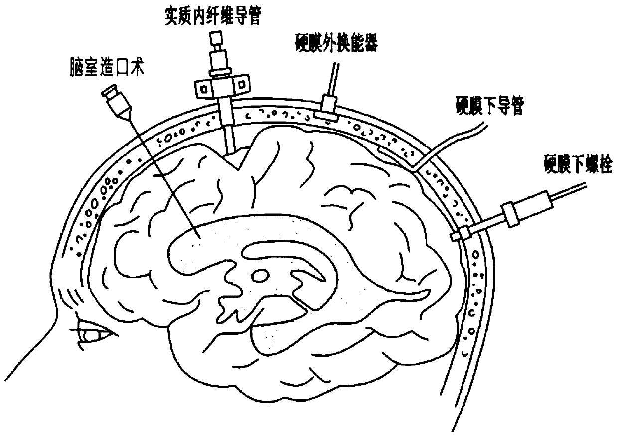
[0008] However, with this method, side effects such as cerebral hemorrhage may occur through the invasive procedure of directly inserting the catheter into the brain parenchyma

Method used


Image

  • Intracranial pressure measuring device
  • Intracranial pressure measuring device
  • Intracranial pressure measuring device

Examples


Embodiment Construction

[0041] Hereinafter, the present invention will be described in detail with reference to the accompanying drawings so that those skilled in the art to which the present invention pertains can easily implement the present invention. However, the present invention can be embodied in many different forms, and is not limited to what is described here. In addition, in the drawings, in order to clearly describe the present invention, parts irrelevant to the description are omitted, and similar reference numerals are assigned to similar parts throughout the specification.

[0042] Throughout this specification, when a part is "connected" to other parts, this includes the case of "direct connection" and the case of "indirect connection" with other devices interposed therebetween.

[0043] Throughout this specification, when a part is located "above", "upper", "upper", "below", "lower", "lower" of another part, this includes situations where one part is in contact with another part and ...


PUM


Abstract

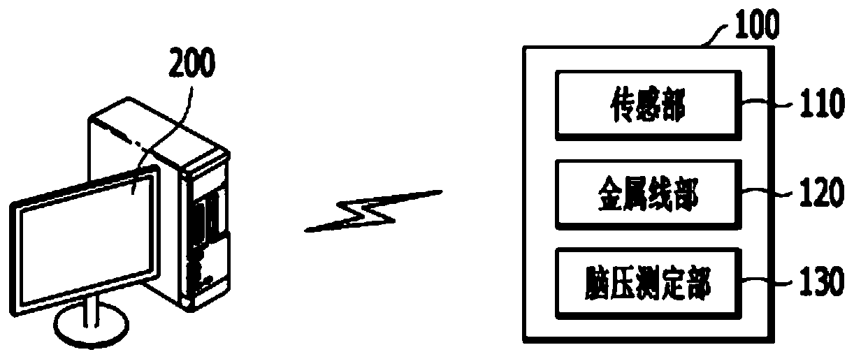
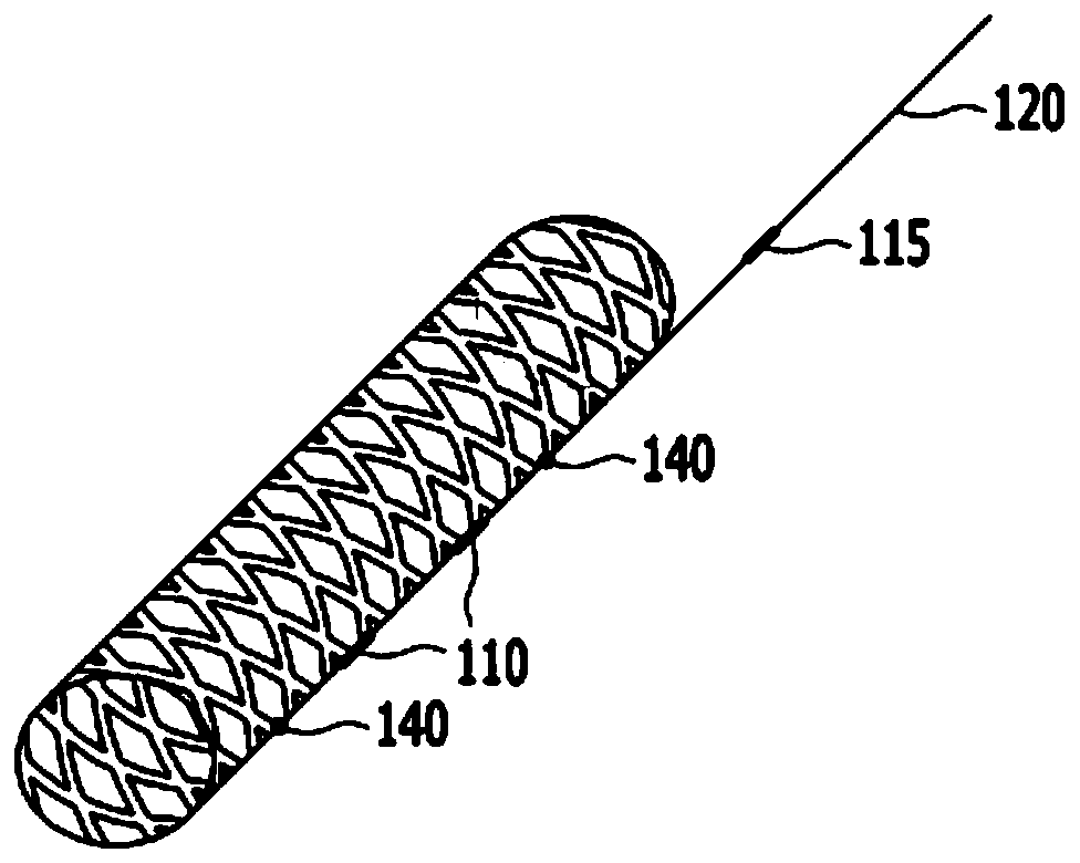
The present invention relates to an intracranial pressure measuring device comprising: a sensor unit for measuring pressure at a predetermined location in a subject's cerebral blood vessel; a wire unit connected to the sensor unit and inserted in the subject to locate the sensor unit at the location; and an intracranial pressure measuring unit for measuring intracranial pressure on the basis of the measured pressure.

Description

technical field [0001] The present invention relates to a device for measuring brain pressure. Background technique [0002] Generally, with the aging of the society, the number of elderly people at home increases, and the concern for the welfare and management of the elderly gradually increases. From multiple perspectives, new methods begin to approach the health management of the elderly, focusing on health diagnosis based blood pressure measurement. [0003] With development, if the integration of the cranial suture is completed, the brain is completely surrounded by the hard skull. The skull space thus defined consists of brain parenchyma (about 1400g, 80%), cerebrospinal fluid (150ml, 10%), and blood (150ml, 10%). If the volume of one of the above three parts increases, the volume of the other parts will increase. The volume will decrease, which will compensate for the increase in pressure (Mon-ro-Kelli hypothesis). [0004] However, if this compensation is not suffi...

Claims


Application Information

Patent Timeline
Patent Type & Authority Applications(China)
IPC IPC(8): A61B5/03
CPCA61B5/031A61B5/6876A61B5/6862A61B5/0215A61B5/03
Inventor 李德熙朴仲澈李承柱金成勋全相范黄善文金泰一黄昌模孟准永
Owner THE ASAN FOUND
Learn More