Unlock instant, AI-driven research and patent intelligence for your innovation.
A double-sided high-gloss steel ring cutting equipment
What is Al technical title?
Al technical title is built by PatSnap Al team. It summarizes the technical point description of the patent document.
A cutting equipment and steel ring technology, applied in the field of double-sided high-gloss steel ring cutting equipment, can solve the problems of bending, low production efficiency, time-consuming and labor-intensive annular abrasive tools, etc., to achieve flexible equipment, high production efficiency, and high quality. Effect
Active Publication Date: 2020-05-19
NANTONG RUNYA ELECTROMECHANICAL TECH CO LTD
View PDF7 Cites 0 Cited by
Summary
Abstract
Description
Claims
Application Information
AI Technical Summary
This helps you quickly interpret patents by identifying the three key elements:
Problems solved by technology
Method used
Benefits of technology
Problems solved by technology
[0002] Usually, when the steel plate is processed into circular round steel, it is often necessary to cut and grind the existing steel plate. Generally speaking, the steel plate needs to be cut by one machine, and then put into the grinder for grinding. When two When the steps are separated, the production efficiency is low. At the same time, due to the nature of the structure of the cut ring, it is easy to cause stress concentration and bending during transportation. At the same time, it is very inconvenient to polish the steel of the ring type, especially when it needs to be reversed. When both sides are polished, since the ring does not need to be polished, it is time-consuming and labor-intensive to set up a ring abrasive tool separately, and the production cost is high. Therefore, a double-sided high-gloss steel ring cutting equipment is needed to solve the above problems
Method used
Image
Click on the blue label to locate the original text in one second.
Reading with bidirectional positioning of images and text.
Examples
Embodiment Construction
[0024] Combine below Figure 1-6 The present invention is described in detail, wherein, for the convenience of description, the orientations mentioned below are defined as follows: figure 1 The up, down, left, right, front and back directions of the projection relationship itself are the same.
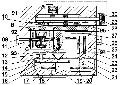
[0025] combined with Figure 1-6 The mechanical structure of the double-sided high-gloss steel ring cutting equipment mainly includes an extrusion close mechanism 91 , an upper grinding and cutting mechanism 92 , a thimble assembly 95 , a lower grinding suction cup mechanism 93 , a feeding assembly 94 and a ring width adjustment assembly 96 .
[0026] Adjusting the above-mentioned ring width adjustment assembly 96 can change the ring width of the steel ring cut out by the equipment. The above-mentioned extrusion close mechanism 91 can make the above-mentioned upper grinding and cutting mechanism 92 close to the above-mentioned extrusion close-to mechanism 91 and contact the steel plat...
PUM
Abstract
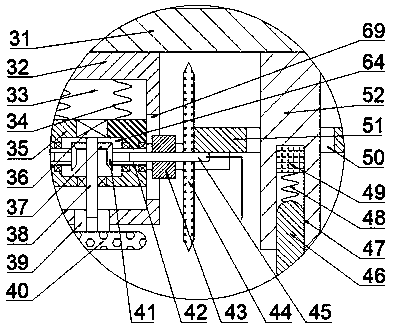
The invention discloses double-sided high-gloss steel ring cutting equipment. The double-sided high-gloss steel ring cutting equipment comprises an extruding and attaching mechanism 91, an upper grinding and cutting mechanism 92, an ejector pin assembly 95, a lower grinding suction cup mechanism 93, a knife feeding assembly 94 and an annular width adjusting assembly 96; the upper grinding and cutting mechanism 92 comprises a machine body 30, a first sliding cavity 27, a sliding plate 31, a first spring 10, a first fixing block 32, a second sliding cavity 33, a limiting groove 69, a first sliding block 35, a second spring 34, a first cavity 64, a first motor 36, a first driving shaft 38, a first spline sleeve 39 and a first grinding disc 40; the lower grinding suction cup mechanism 93 located below the upper grinding and cutting mechanism 92 comprises a second cavity 22, a second motor 19, a second driving shaft 18, a first circular gear 17, a groove 15 and a suction cup 16. The steel ring cutting device has the advantages that simultaneous grinding of the upper and lower surfaces of steel ring while cutting steel plate as steel ring, the production efficiency is high, the grindingthickness is flexible and adjustable, and the equipment can be circularly produced, and is safe and reliable.
Description
technical field [0001] The invention relates to a double-sided high-gloss steel ring cutting device, and mainly relates to the field of steel plate processing. Background technique [0002] Usually, when the steel plate is processed into circular round steel, it is often necessary to cut and grind the existing steel plate. Generally speaking, the steel plate needs to be cut by one machine, and then put into the grinder for grinding. When two When the steps are separated, the production efficiency is low. At the same time, due to the nature of the structure of the cut ring, it is easy to cause stress concentration and bending during transportation. At the same time, it is very inconvenient to polish the steel of the ring type, especially when it needs to be reversed. When both sides are polished, since the ring does not need to be polished, it is time-consuming and labor-intensive to set up a ring abrasive tool separately, and the production cost is high. Therefore, a double-...
Claims
Application Information
Patent Timeline
Application Date:The date an application was filed.
Publication Date:The date a patent or application was officially published.
First Publication Date:The earliest publication date of a patent with the same application number.
Issue Date:Publication date of the patent grant document.
PCT Entry Date:The Entry date of PCT National Phase.
Estimated Expiry Date:The statutory expiry date of a patent right according to the Patent Law, and it is the longest term of protection that the patent right can achieve without the termination of the patent right due to other reasons(Term extension factor has been taken into account ).
Invalid Date:Actual expiry date is based on effective date or publication date of legal transaction data of invalid patent.

