Shock absorption and energy dissipation anti-falling beam device for railway bridge

A technology for anti-fall beams and bridges, applied in bridges, bridge construction, bridge parts, etc., can solve the problems of anti-fall beam stoppers such as lack of seismic energy consumption capacity, complicated design, increased cost, etc., and achieve good application prospects, The effect of simplifying the design and increasing the contact area

Pending Publication Date: 2019-07-26
CHINA RAILWAY ERYUAN ENG GRP CO LTD
View PDF0 Cites 5 Cited by
  • Summary
  • Abstract
  • Description
  • Claims
  • Application Information

AI Technical Summary

Problems solved by technology

[0007] The purpose of the present invention is to overcome the lack of earthquake energy dissipation capacity of the existing anti-fall beam stoppers, poor adaptability in high-intensity earthquake areas, and the need to add a separate damper device to consume energy, and the separate damper device not only increases the cost , it is also necessary to consider the space and location of the installation, which complicates the design and other shortcomings, and provides a shock-absorbing and energy-consuming anti-falling beam device for railway bridges

Method used


Image

  • Shock absorption and energy dissipation anti-falling beam device for railway bridge
  • Shock absorption and energy dissipation anti-falling beam device for railway bridge
  • Shock absorption and energy dissipation anti-falling beam device for railway bridge

Examples


Embodiment 1

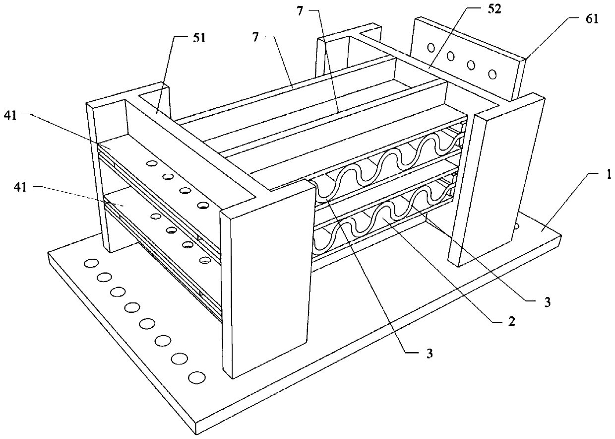
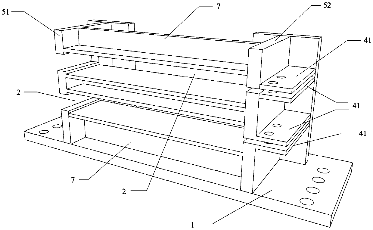
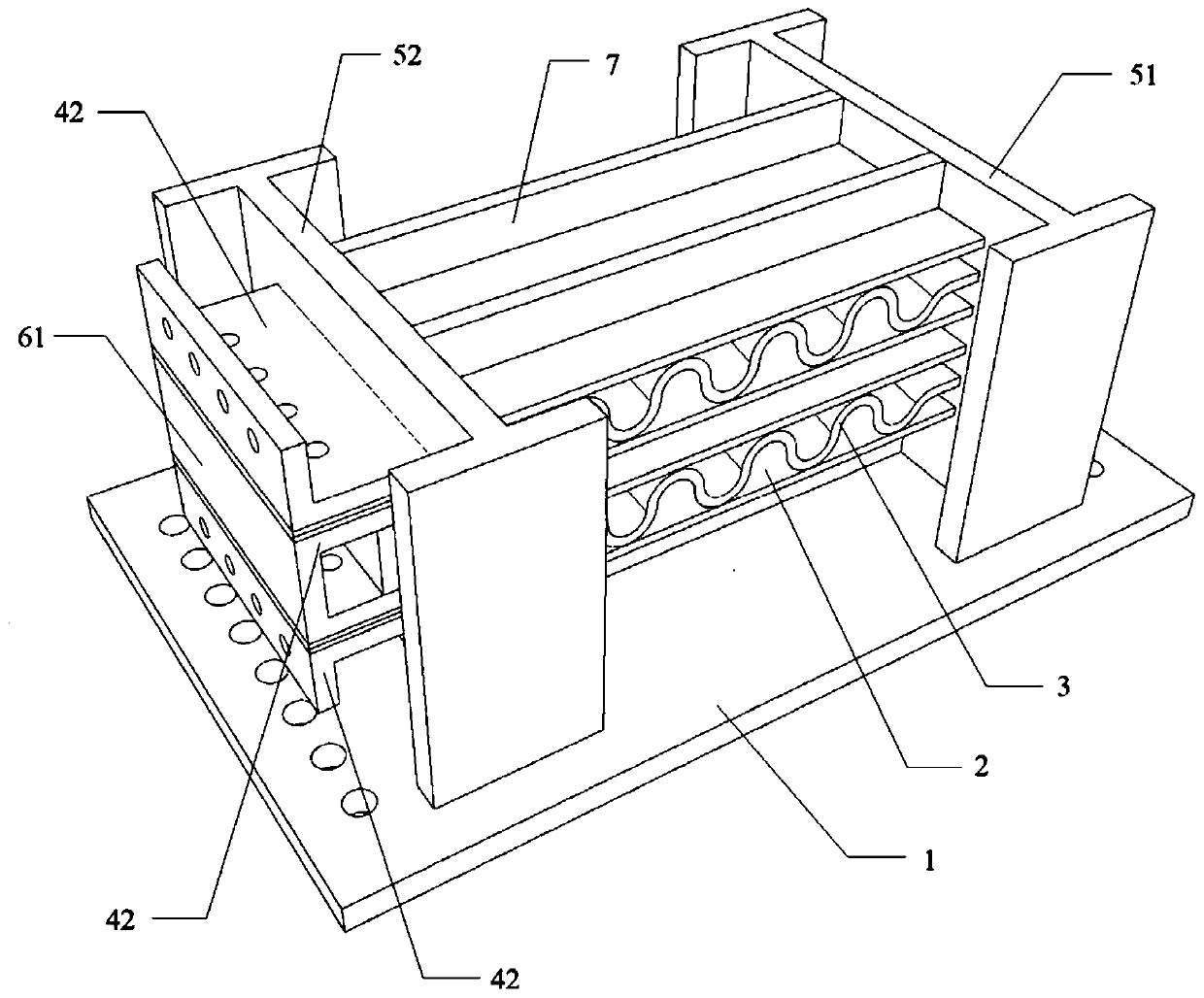
[0034] Such as Figure 1-3As shown, a kind of shock-absorbing and energy-dissipating anti-drop beam device for railway bridges according to the present invention includes a steel base plate 1, a partition one 51 and a partition two 52, and the partition one 51 and the partition two 52 are all connected to the bottom plate 1, and the bottom plate 1 is provided with at least one limiting groove 2, such as the example of this embodiment, there are two limiting grooves 2, the specific number is determined according to the energy consumption capacity requirement and the installation space, two Two limit grooves 2 are aligned and arranged in sequence along the height direction. Specifically, the limit groove 2 can be formed by two frames, or two side plates, or one side is a frame and the other side is a side plate. In this implementation For example, it is formed by two steel side plates, and a limiting groove 2 is formed between the two side plates. The height of the limiting groo...

Embodiment 2

[0038] A shock-absorbing and energy-dissipating anti-drop beam device for a railway bridge according to the present invention has the same structure as that of Embodiment 1, the difference being that all the corrugated plates 3 are replaced by corrugated steel pipes, and each corrugated steel pipe The two ends are replaced by tubular sections, such as flat, that is, the cross section of the tubular section is oval, and the tubular sections at both ends are used to connect the first splint 41 and the second splint 42 respectively. If bolted connection is adopted, preferably, the first splint The shape of the inner wall of 41 and the second splint 42 is adapted to the shape of the outer wall of the tubular section, and the through hole is adapted to the shape of the tubular section, so that the tubular sections at both ends can be connected with the first splint 41 and the second splint 42 respectively.


PUM


Abstract

The invention discloses a shock absorption and energy dissipation anti-falling beam device for a railway bridge. The shock absorption and energy dissipation anti-falling beam device for the railway bridge comprises a bottom plate, wherein the bottom plate is connected with at least one limiting slot, all the limiting slots are formed in sequence in the height direction, at least one corrugated plate is arranged in each limiting slot, the vertical cross section of each corrugated plate is in a wave shape, the width of each limiting slot is matched and corresponds to the total width of all the corrugated plates, one ends of all the corrugated plates in each limiting slot are connected to first ends of the limiting slots, the other ends of the corresponding corrugated plates are connected tomovable members, and each movable member is slidably connected with a second end of the corresponding limiting slot. According to the shock absorption and energy dissipation anti-falling beam device for the railway bridge, the energy dissipation members are effectively combined with the anti-falling beam device, so that the anti-falling beam device has remarkable energy dissipation capacity; and the structure form is reasonable and concise, the manufacturing cost is greatly reduced, installation and replacement are convenient, the installation height space is effectively saved under the same energy dissipation capacity, and the bridge structure is effectively protected.

Description

technical field [0001] The invention relates to the technical field of anti-falling beam energy consumption of railway bridges, in particular to a vibration-absorbing energy-consuming anti-falling beam device for railway bridges. Background technique [0002] The anti-falling beam device is the key structure of bridge anti-seismic. It is mainly used to prevent the falling beam caused by the excessive relative displacement between the upper structure and the lower structure. Therefore, the anti-falling beam device is generally used in bridge engineering in earthquake areas. [0003] In the prior art, the anti-fall beam devices of highway bridges in my country generally adopt concrete stoppers, high-strength steel tie rods, high-strength steel cables, etc., while the anti-fall beam devices of railway bridges generally adopt various types based on I-beam processing. However, the anti-fall beam devices of the above-mentioned forms generally have certain limitations, which are spe...

Claims


Application Information

Patent Timeline
Patent Type & Authority Applications(China)
IPC IPC(8): E01D19/00
CPCE01D19/00
Inventor 董俊曾永平陈克坚杨国静刘力维庞林郑晓龙陶奇苏延文徐昕宇周川江颜永逸
Owner CHINA RAILWAY ERYUAN ENG GRP CO LTD
Why Eureka
Try Eureka