Steel bar truss floor support plate with clamping grooves

A technology of reinforced trusses and clamping grooves, which is applied in the field of reinforced truss floor decks, which can solve the problems of time-consuming and labor-intensive keel installation and high hardness of cement boards, and achieve the effects of reducing construction difficulty, facilitating leveling, and reducing construction difficulty

Pending Publication Date: 2021-05-07
SHANGHAI OPEN STEEL JOIST
View PDF0 Cites 0 Cited by
  • Summary
  • Abstract
  • Description
  • Claims
  • Application Information

AI Technical Summary

Problems solved by technology

[0002] The traditional steel truss floor deck has no connection structure for the ceiling. After the floor deck is poured and formed, for the installation of the ceiling, it is necessary to install the keel bracket on the surface of the cement slab; the keel bracket is mostly fixed with the cement slab through self-tapping screws. , the hardness of the cement board is high, and the installation of the keel is time-consuming and laborious

Method used


Image

  • Steel bar truss floor support plate with clamping grooves
  • Steel bar truss floor support plate with clamping grooves
  • Steel bar truss floor support plate with clamping grooves

Examples


Embodiment 1

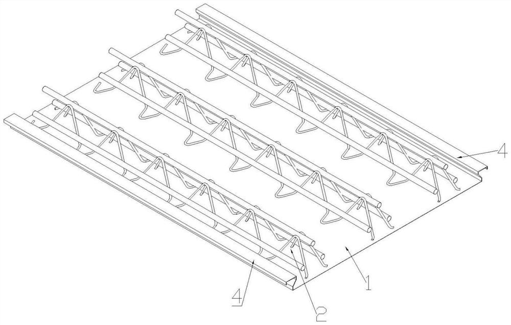
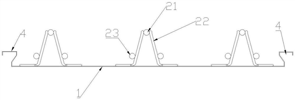
[0026] Such as figure 1 and figure 2 As shown, the present invention proposes a steel bar truss 2 floor bearing plate with a clamping groove 4, including a bottom plate 1, a steel bar truss 2 and a ceiling connector 3, the steel bar truss 2 is fixed on the bottom plate 1, and the back of the bottom plate 1, that is, the back A clamping groove 4 is provided on one side of the steel truss 2, and the clamping groove 4 is arched toward the side connecting the steel truss 2; the ceiling connector 3 is clamped in the clamping groove 4, and the ceiling connector 3 and the ceiling 5 Make the connection.

[0027] The clamping groove 4 cooperates with the design of the ceiling connector 3, which is convenient to use self-tapping screws to connect the gypsum board or other decorative boards to the bottom of the floor deck to form a suspended ceiling, which reduces the difficulty of construction and protects the overall structure of the floor deck. Self-tapping nails are not only labor...

Embodiment 2

[0035] Embodiment 2 has the same overall structure as Embodiment 1, except that the ceiling connector 3 is a spring connecting piece 34 , the structure of the locking groove 4 and the position relative to the bottom plate 1 are different.

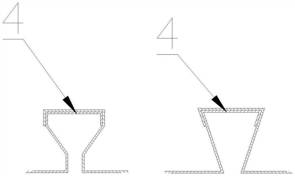
[0036] Such as Image 6 As shown, the clamping groove 4 includes any one of the dovetail groove 41, the T-shaped groove 42 or the double inclined groove 43, but is not limited to one of them, and the slot hole with the clamping effect can be used as the embodiment of the present invention As an example, the position of the clamping groove 4 is based on actual engineering requirements. If it is necessary to realize the overlap between the floor decks, it can be placed on both sides of the bottom plate 1. If not, it can also be placed as Image 6 As shown, it is placed near the middle of the bottom plate 1.

[0037] In this embodiment, the ceiling connector 3 is a spring connecting piece 34, and the spring connecting piece 34 includes two el...


PUM


Abstract

The invention provides a steel bar truss floor supportplate with the clamping grooves. The steel bar truss floor support comprises a bottom plate, a steel bar truss and a suspended ceiling connecting piece, wherein the steel bar truss is fixed to the bottom plate, the clamping grooves are formed in the back face, namely away from the side of the steel bar truss, of the bottom plate, the clamping grooves are arched towards the side connected to the steel bar truss, the suspended ceiling connecting piece is clamped in the clamping grooves, and the suspended ceiling connecting piece is connected to the suspended ceiling, so that the steel bar truss floor support plate with suspension ribs having the advantages that the cost is effectively saved, the suspended ceiling is convenient to install and level, and the overall structure of the floor support plate is protected is provided.

Description

technical field [0001] The invention relates to the technical fields of architecture and civil engineering, in particular to a reinforced truss floor bearing plate with clamping slots. Background technique [0002] The traditional steel truss floor deck has no connection structure for the ceiling. After the floor deck is poured and formed, for the installation of the ceiling, it is necessary to install the keel bracket on the surface of the cement slab; the keel bracket is mostly fixed with the cement slab through self-tapping screws. , The hardness of the cement board is high, and the installation of the keel is time-consuming and laborious. Contents of the invention [0003] The object of the present invention is to propose a reinforced truss floor deck with suspension ribs which is effective in cost saving, convenient for ceiling installation and leveling, and protects the overall structure of the floor deck. [0004] In order to achieve the above purpose, the present ...

Claims


Application Information

Patent Timeline
Patent Type & Authority Applications(China)
IPC IPC(8): E04B5/38E04B5/48
CPCE04B5/38E04B5/48
Inventor 陈明
Owner SHANGHAI OPEN STEEL JOIST
Why Eureka
Try Eureka