
Blind plug fluid connector with spring not exposed on a flow channel

A connector and flow channel technology, applied in the field of blind plug fluid connectors, can solve the problems of complex design and processing, relatively high requirements for spring materials, etc., and achieve the effect of saving costs

Inactive Publication Date: 2019-07-26
万硕(成都)航空科技有限公司
View PDF8 Cites 0 Cited by
  • Summary
  • Abstract
  • Description
  • Claims
  • Application Information

AI Technical Summary

Problems solved by technology

[0003] The technical problem to be solved by the present invention is that all the compression springs of the connector are exposed in the middle of the flow channel, which has a great influence on the flow rate in the flow channel. In the application, the material requirements for the spring are relatively high, and some of the springs are conical tower springs, and the design and processing are complicated. , which affects the size of the flow in the channel

Method used


Image

  • Blind plug fluid connector with spring not exposed on a flow channel
  • Blind plug fluid connector with spring not exposed on a flow channel
  • Blind plug fluid connector with spring not exposed on a flow channel

Examples


Embodiment 1

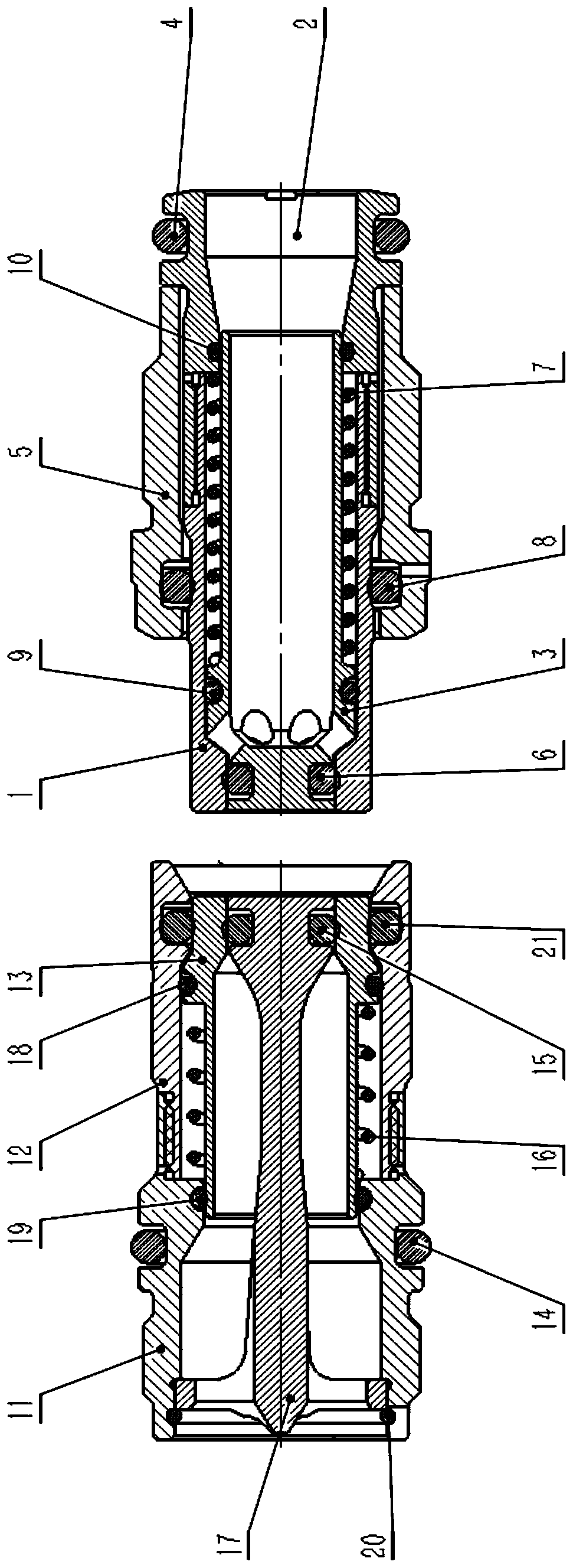
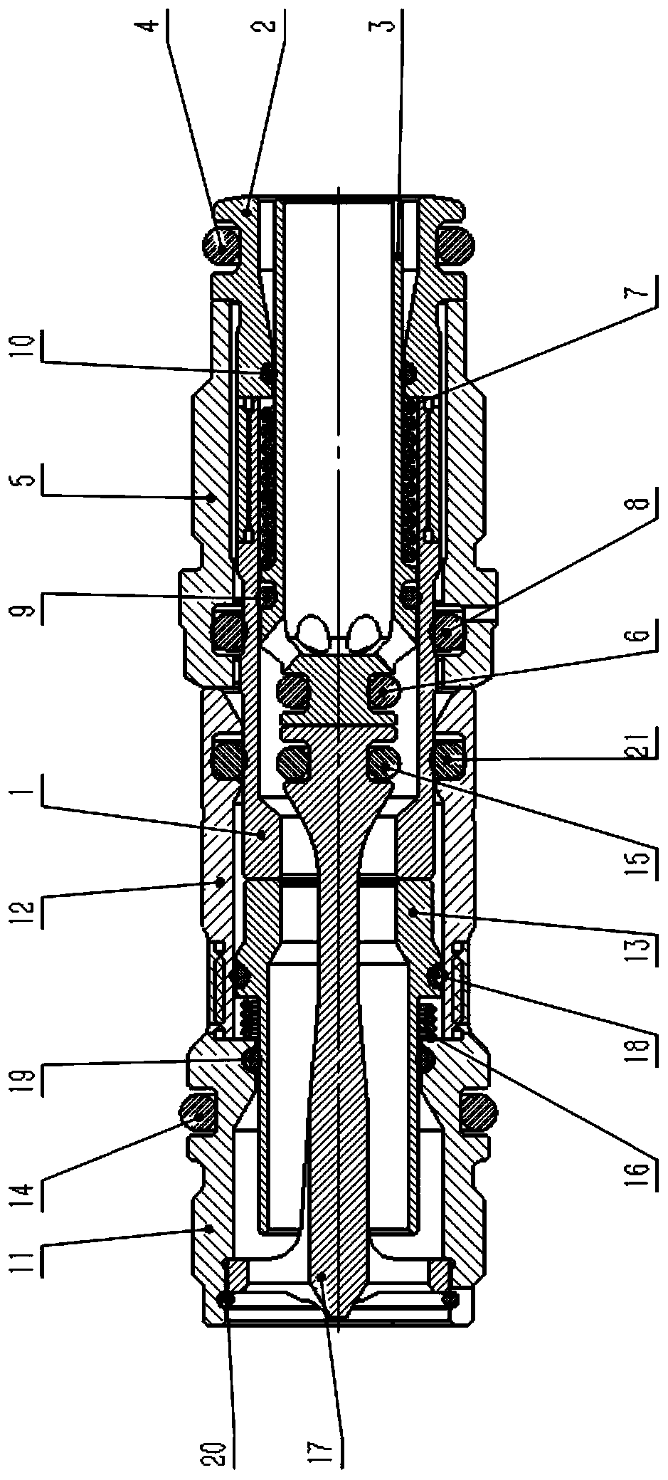
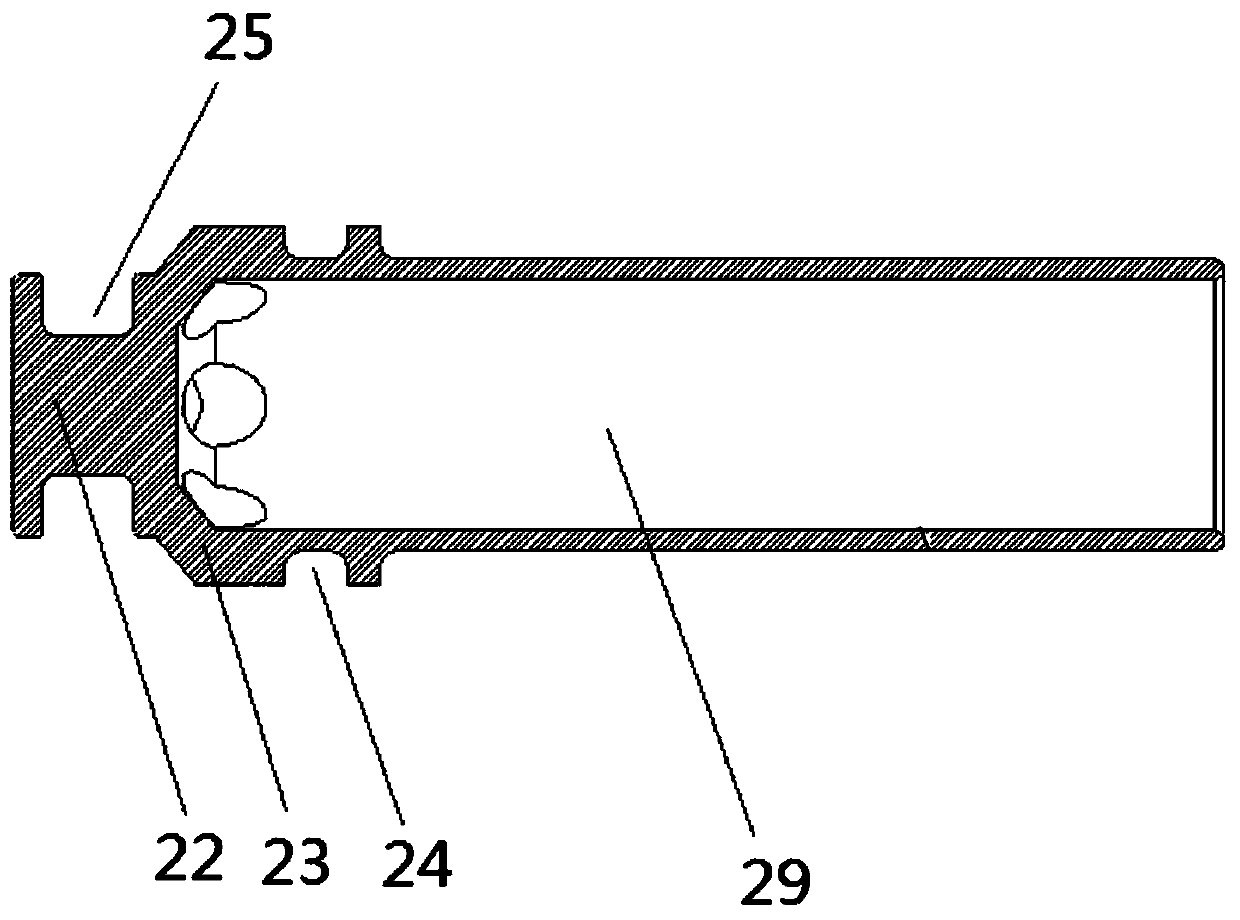
[0027] Such as Figure 1 to Figure 5 As shown, the present invention is a blind plug fluid connector whose spring is not exposed to the flow channel, including a male end connector and a female end connector, and the male end connector includes a first male main shaft sleeve 1 and a second male end The main shaft sleeve 2, the first male end main shaft sleeve 1 and the second male end main shaft sleeve 2 are connected through threads, and the first male end main shaft sleeve 1 is provided with a first passage 26 and a second passage 27, the first passage 26 and the second main shaft sleeve 2 The second channel 27 communicates, the diameter of the first channel 26 is smaller than the second channel 27, and the connection between the first channel 26 and the second channel 27 is a tapered surface; the second male end main shaft sleeve 2 is provided with a third channel 30 , the third channel 30 communicates with the second channel 27 , the third channel 30 is a bell mouth struct...

Embodiment 2

[0035] Such as Figure 1 to Figure 5 As shown, on the basis of Embodiment 1, the second male end main shaft sleeve 2 is also provided with a first vent hole, and the first air vent hole communicates with the male end spring 7, and the first female end main shaft sleeve 11 There are also several second air holes on the top, and the second air holes communicate with the female end spring 16. The first air hole and the second air hole provided can ensure that the female end spring 16 and the male end spring 7 can be kept in contact with the external air pressure. Connected state, so as to ensure the normal compression and rebound of the spring.

[0036] The second male end main shaft sleeve 2 is also provided with an eighth groove, and a first sealing ring 4 is also arranged in the eighth groove; the male end connector is also provided with a mounting nut 5, the The mounting nut 5 is connected to the first male end main shaft sleeve 1 and the second male end main shaft sleeve 2,...


PUM


Abstract

The invention discloses a blind plug fluid connector with a spring not exposed on a flow channel. The blind plug fluid connector comprises a male end connector and a female end connector matched withthe male end connector, the male end connector comprises a first male end main shaft sleeve and a second male end main shaft sleeve, and the female end connector comprises a first female end main shaft sleeve and a second female end main shaft sleeve. When the male end connector is connected with the female end connector, the first male end main shaft sleeve stretches into the second female end main shaft sleeve and pushes a female end valve core shaft sleeve to move, meanwhile, a female end valve core pushes a male end valve core to move, and therefore the flow channel in the female end connector and the male end connector is in a communication state. Since the male end valve core is sleeved with a male end spring, and the female end valve core shaft sleeve is sleeved with a female end spring, when the female end connector and the male end connector are in a communicating state, the male end spring and the female end spring are prevented from affecting the flow in the flow channel, meanwhile, the spring is prevented from adopting higher-cost materials, and the cost is saved.

Description

technical field [0001] The invention relates to the technical field of connectors, in particular to a blind plug fluid connector whose spring is not exposed to the flow channel. Background technique [0002] Fluid connectors are usually used at the connection between the cooling mechanism and the main circulation system in the liquid cooling system. As a key component of the liquid cooling system, the cooling mechanism is equipped with heating components and allows it to exchange heat with its own internal coolant to achieve The purpose of heat dissipation and cooling. In the prior art, both the male end joint and the female end joint of the fluid connector are provided with a movable spool, and the movable spool is arranged on the compression spring, and the other point of the compression spring is provided with a spring retaining ring or a fixed spool, and finally through The snap ring is stuck on the spring retainer or the end of the fixed valve core to achieve a fixed e...

Claims


Application Information

Patent Timeline
Patent Type & Authority Applications(China)
IPC IPC(8): F16L37/32
CPCF16L37/32
Inventor 张彬
Owner 万硕(成都)航空科技有限公司
Learn More