Microwave oven

A microwave oven and oven door technology, applied in the field of microwave ovens, can solve the problems of short circuit, easy flow of condensed water, affecting user safety, etc., and achieve the effect of avoiding water on the table area and avoiding short circuit of circuit devices

Active Publication Date: 2019-07-26
GUANGDONG MIDEA KITCHEN APPLIANCES MFG CO LTD +1
6 Cites 1 Cited by

AI-Extracted Technical Summary

Problems solved by technology

Most of the steam discharged by the exhaust device is directly discharged into the air, and a small part can be cooled into condensed ...

Method used

Further, the microwave oven also includes a hot air assembly (not shown), the hot air assembly is fixed on the outside of the cavity 20, the hot air assembly can generate hot air, the hot air outlet of the hot air assembly communicates with the cavity 20, and can move toward the cavity Into the hot air within 20. The bottom plate assembly 12 is provided with a second water receiving tank 124 . The second water receiving tank 124 is located directly below the connection between the hot air assembly and the chamber body 20 , and communicates with the first water receiving box 40 . Since the cavity 20 will be provided with a mesh to communicate with the hot air assembly, part of the steam will be discharged from the mesh, and condensed into a water flow, which will penetrate from the installation fit gap between the hot air assembly and the cavity 20, so through the bottom plate assembly 12 is provided with a second water receiving tank 124, which can recover the condensed water permeated from the installation fit gap between the hot air component and the cavity 20 to the first water receiving box 40, preventing the circuit components from being wetted. In this embodiment, the first water receiving tank 121 and the second water receiving tank 124 jointly form a triangular tank-like structure.
In the present embodiment, in order to pour out the condensed water in the first water receiving box 40 and the second water receiving box 60 in time, so the first water receiving box 40 is movably connected with the bottom plate assembly 12, and the second receiving water box The water box 60 is also in movably communication with the bottom plate assembly 12 . Similarly, in order to facilitate timely replenishment of water in the water tank 53 , the water tank 53 is movably connected with the bottom plate assembly 12 . Specifically, a drawing port is provided on the side of the bottom plate assembly 12, and the drawing port is located on the same side as the furnace door assembly 11, and the first water receiving box 40, the second water receiving box 60 and the water tank 53 can be drawn from the drawing port. out. In addition, the first water receiving box 40 , the second water receiving box 60 and the water tank 53 can all be engaged with the bottom plate assembly 12 through buckles to avoid shaking or moving. In order to facilitate the pulling of the water tank 53, a puller 63 is provided on the water tank 53. The puller 63 is generally in the shape of a long strip and is located on the outer side of the water tank 53. A handle or a recessed handle can be set on the puller 63. Slots are for user actions. The second water receiving box 60 is disposed on the drawer 63 , and optionally, the second water receiver 60 and the drawer 63 are integrally formed.
In the present invention, by setting the drain port 321 at the intake cover 30, since the intake cover 30 is connected to the cavity 20 and the shell, the steam in the cavity 20 reaches the intake cover 30 after a long time pipeline, so part of the steam is condensed into condensed water, and the steam and condensed water are split in the air intake hood 30, wherein the steam can be discharged from the air outlet 131 on the casing, while the condensed water is deposited in the air intake hood 30 and passed through The drain port 321 is discharged into the first water receiving box 40, so as to prevent the condensed water from dripping between the shell and the cavity 20 to cause a short circuit of the circuit device, and also to prevent the condensed water from being directly discharged to the outside along with the steam to cause surface water accumulation.
Please refer to Fig. 14, the arrow in Fig. 14 is the water flow direction, in one embodiment, the water tank 53 and the first water receiving box 40 are arranged along the extension direction of the lower end of the furnace door assembly 11, that is, arranged along the transverse direction The top surface of the water tank 53 is provided with a water guide groove 531, the water guide groove 531 is facing the lower end of the furnace door assembly 11, to receive the condensed water dripping from the furnace door assembly 11, and the bottom of the water guide groove 531 is provided with a water guide hole 532 to be connected with the furnace door assembly 11. The first water receiving box 40 is connected. In this embodiment, the water guiding groove 531 extends along the extension direction of the lower end of the furnace door assembly 11, and partly extends into the first water receiving box 40, and the part of the water guiding groove 531 extending into the first water receiving box 40 is provided There is a water guide hole 532 to discharge the collected condensed water into the first water receiving box 40 . In the embodiment of the present invention, if the length of the first water receiving box 40 is set too large, it will cause too much space occupied by the microwave oven, so in this embodiment, the length of the first water receiving box 40 is shorter than that of the oven door assembly 11. The length of the lower end leaves some space for the water supply tank 53 to place, which can reduce the occupation of space. The diversion groove provided on the water tank 53 and the first water receiving box 40 jointly receive the condensed water dripping from the furnace door assembly 11 to prevent the condensed water from dripping onto the bottom plate assembly 12 .
Please refer to Fig. 18 and Fig. 19, the arrow in the figure is the flow direction of the steam, in one embodiment, the microwave oven also includes an exhaust hood 70, and the exhaust hood 70 is arranged on the shell and is set on the air outlet 131 . The exhaust hood 70 can not only prolong the flow path of the steam, reduce the temperature of the steam, but also disperse the steam, so as to avoid scalding the user due to concentrated discharge of the steam. Specifically, the exhaust hood 70 is detachably connected to the housing, for example, the exhaust hood 70 and the housing are fixed by screws or buckles. The exhaust hood 70 is provided with a plurality of exhaust passages 72, and the plurality of exhaust passages 72 are arranged upwardly through the exhaust hood 70, and the plurality of exhaust passages 72 are all communicated with the air outlet 131 on the casing, thereby dispersing the steam discharge.
Please refer to Fig. 21 in conjunction with, in one embodiment, be provided with stop member 80 in exhaust cover 70, stop member 80 comprises substrate 81 and baffle plate 82, and the bottom surface of substrate 81 and exhaust cover 70 is fixed, The baffle 82 is connected to the base plate 81 and cons...

Abstract

The invention discloses a microwave oven. The microwave oven comprises a shell, a cavity, an air inlet cover and a water collecting piece, wherein an air outlet is formed in the shell, the cavity is formed in the shell, an exhaust port is formed in the cavity, the air inlet cover is arranged between the cavity and the shell, an air inlet channel which communicates with the air outlet and the exhaust port and a water outlet which communicates with the air inlet channel are formed in the air inlet cover, and the water collecting piece is arranged below the air inlet cover and communicates with the water outlet so as to collect condensate water in the air inlet channel. According to the technical scheme of the microwave oven, the condensate water formed by steam can be prevented from making contact with a circuit device.

Application Domain

Domestic stoves or rangesDoors for stoves/ranges +5

Technology Topic

Microwave ovenElectrical and Electronics engineering +1

Image

  • Microwave oven
  • Microwave oven
  • Microwave oven

Examples

  • Experimental program(1)

Example Embodiment

[0047] The following will clearly and completely describe the technical solutions in the embodiments of the present invention with reference to the accompanying drawings in the embodiments of the present invention. Obviously, the described embodiments are only part of the embodiments of the present invention, not all of them. Based on the embodiments of the present invention, all other embodiments obtained by persons of ordinary skill in the art without creative efforts fall within the protection scope of the present invention.
[0048] It should be noted that if there is a directional indication (such as up, down, left, right, front, back...) in the embodiment of the present invention, the directional indication is only used to explain the position in a certain posture (as shown in the accompanying drawing). If the specific posture changes, the directional indication will also change accordingly.
[0049] In addition, if there are descriptions involving "first", "second" and so on in the embodiments of the present invention, the descriptions of "first", "second" and so on are only for descriptive purposes, and should not be interpreted as indicating or implying Its relative importance or implicitly indicates the number of technical features indicated. Thus, the features defined as "first" and "second" may explicitly or implicitly include at least one of these features. In addition, the meaning of "and/or" appearing in the whole text includes three parallel schemes, taking "A and/or B as an example", including scheme A, scheme B, or schemes satisfying both A and B. In addition, the technical solutions of the various embodiments can be combined with each other, but it must be based on the realization of those skilled in the art. When the combination of technical solutions is contradictory or cannot be realized, it should be considered that the combination of technical solutions does not exist , nor within the scope of protection required by the present invention.
[0050] The invention provides a microwave oven.
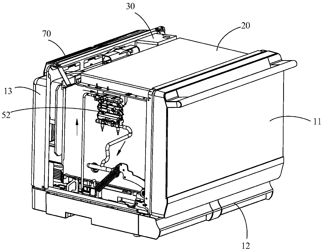
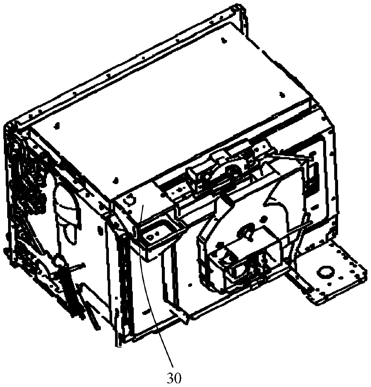
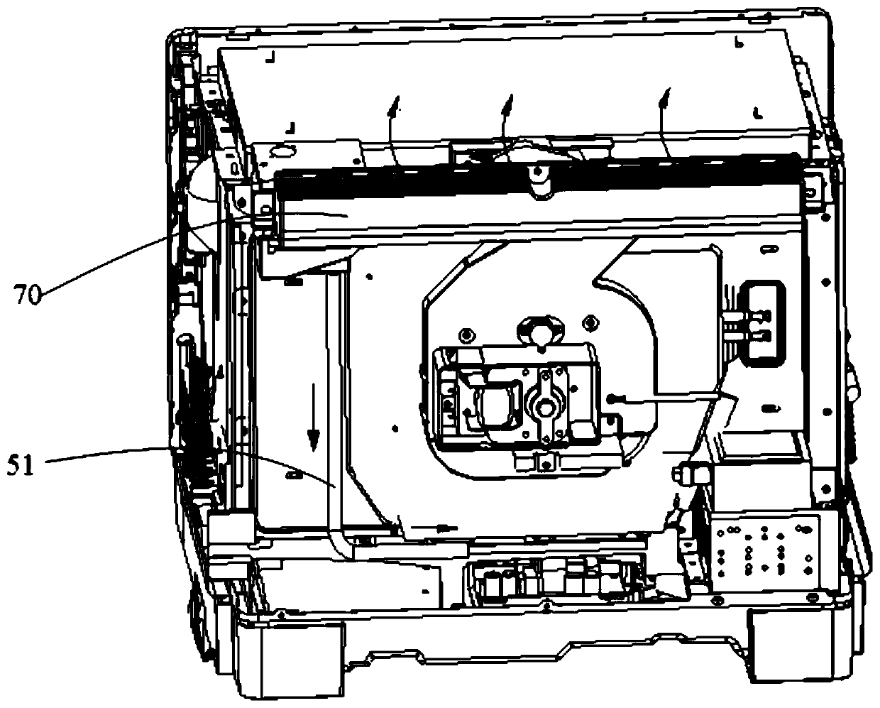
[0051] In the embodiment of the present invention, please refer to Figure 1 to Figure 5, the microwave oven includes a shell, a cavity 20, an air intake cover 30, a water receiving member, an evaporator 52, a water tank 53 and other components.
[0052] Please refer to Figure 17 , wherein, an air outlet 131 is provided on the casing, the casing is generally in the shape of a cube, and the air outlet 131 is arranged on the side wall or the top wall of the casing. The casing can include a furnace door assembly 11 and a bottom plate assembly 12. The furnace door assembly 11 covers the opening of the cavity 20 and can be opened and closed relative to the cavity 20. The bottom plate assembly 12 is located at the bottom of the cavity 20 for supporting the cavity 20. . In addition, the casing also includes a rear shell 13 , which is arranged opposite to the furnace door assembly 11 , and the air outlet 131 is arranged on the rear shell 13 .
[0053] The cavity 20 is arranged in the casing, and the cavity 20 is provided with an exhaust port 21 , and the exhaust port 21 is used to discharge excess steam in the cavity 20 . Usually, there is a circumferential gap between the cavity 20 and the housing for accommodating devices such as the evaporator 52 and electronic components.
[0054] Please refer to Figure 16 , the air intake cover 30 is arranged between the cavity 20 and the shell, and has an air intake channel 313 and a drain port 321 communicating with the air intake channel 313, and the air intake channel 313 communicates the air outlet 131 with the exhaust port 21, thereby making the cavity The steam in the body 20 is discharged to the outside through the gas outlet 131 on the casing.
[0055] The water receiving member is disposed under the air intake cover 30 and communicates with the drain port 321 to receive the condensed water in the air intake passage 313 . Specifically, the water receiving part includes a first water receiving box 40 (such as Figure 12 Shown) and drain pipe 51, the first water receiving box 40 is arranged below the intake cover 30. Optionally, the first water receiving box 40 is disposed on the bottom plate assembly 12 to enable the air intake cover 30 to drain water from top to bottom. In addition, the first water receiving box 40 can also be arranged on the side wall of the housing or other positions. One end of the drain pipe 51 is connected to the drain port 321 , and the other end is communicated with the first water receiving box 40 , so as to drain the condensed water in the air intake cover 30 to the first water receiving box 40 . In addition, the water receiving part may also only include the first water receiving box 40 , or the water receiving part may be a water receiving tank disposed on the bottom plate assembly 12 or other structures.
[0056] The evaporator 52 and the water tank 53 are both arranged between the shell and the cavity 20, and the cavity 20 is provided with a steam inlet 22, Figure 4 The middle arrow is the flow direction of the steam. One end of the evaporator 52 communicates with the water tank 53, and the other end communicates with the steam inlet 22. The water in the water tank 53 flows into the evaporator 52, and is evaporated to form steam and then flows into the cavity 20 (please refer to figure 1 and Figure 4 , figure 1 The middle arrows indicate the flow direction of water and steam, Figure 4 The middle arrow is the flow direction of steam). In addition, a water pump 54 is also provided on the connecting pipe between the water tank 53 and the evaporator 52 . The water tank 53 is installed on the base plate assembly 12 , specifically, buckles can be provided on the base plate assembly 12 to clamp the water tank 53 . In addition, a water pump 54 is also mounted on the floor assembly 12 .
[0057] In the present invention, by setting the drain port 321 on the air intake hood 30, since the air intake hood 30 is connected to the cavity 20 and the shell, the steam in the cavity 20 reaches the air intake hood 30 through a long pipeline, Therefore, part of the steam is condensed into condensed water, and the steam and condensed water are split in the air intake hood 30, wherein the steam can be discharged from the air outlet 131 on the shell, while the condensed water is deposited in the air intake hood 30, and is discharged through the drain port 321 It is discharged into the first water receiving box 40, so as to prevent the condensed water from dripping between the shell and the cavity 20 and cause a short circuit of the circuit device, and also prevent the condensed water from being directly discharged to the outside with the steam to cause surface water.
[0058] Please refer to Figure 6 to Figure 11 , the arrows in the figure indicate the direction of water flow. In one embodiment, the bottom plate assembly 12 is provided with a first water receiving tank 121, the bottom of the first water receiving tank 121 is provided with a drain hole 122, the first water receiving box 40 is located directly below the drain hole 122, and the drain pipe 51 and The first water receiving tank 121 is connected. In this embodiment, the first water receiving box 40 communicates with the drain hole 122 and can receive the condensed water discharged from the drain hole 122 . By arranging the first water receiving tank 121 for drainage, the setting of the first water receiving box 40 can be facilitated, so that the first water receiving box 40 can be arranged in a suitable position, and its setting position is more flexible, for example, one near the furnace door assembly 11 side, so that the first water receiving box 40 is pulled out to pour water. In one embodiment, the bottom plate assembly 12 is provided with a tubular joint 123 , and the inner hole of the tubular joint 123 constitutes a part of the first water receiving tank 121 , and the drain pipe 51 is sleeved on the tubular joint 123 . Specifically, the tubular joint 123 is a semicircular joint, and buckles or the like can also be provided on the tubular joint 123 to clamp and fix the drain pipe 51 to prevent the drain pipe 51 from detaching. By directly sheathing the drain pipe 51 on the tubular joint 123 , the installation is simpler and the drain pipe 51 can be prevented from moving. Optionally, the tubular joint 123 extends transversely. In addition, the drain pipe 51 can also directly extend into the first water receiving tank 121 to discharge the condensed water to the first water receiving tank 121 .
[0059] Further, the microwave oven also includes a hot air assembly (not shown), the hot air assembly is fixed on the outside of the cavity 20, the hot air assembly can generate hot air, the hot air outlet of the hot air assembly communicates with the cavity 20, and can be transmitted to the cavity 20. into the hot air. The bottom plate assembly 12 is provided with a second water receiving tank 124 . The second water receiving tank 124 is located directly below the connection between the hot air assembly and the chamber body 20 , and communicates with the first water receiving box 40 . Since the cavity 20 will be provided with a mesh to communicate with the hot air assembly, part of the steam will be discharged from the mesh, and condensed into a water flow, which will penetrate from the installation fit gap between the hot air assembly and the cavity 20, so through the bottom plate assembly 12 is provided with a second water receiving tank 124, which can recover the condensed water permeated from the installation fit gap between the hot air component and the cavity 20 to the first water receiving box 40, preventing the circuit components from being wetted. In this embodiment, the first water receiving tank 121 and the second water receiving tank 124 jointly form a triangular tank-like structure.
[0060] In one embodiment, the bottom plate assembly 12 is composed of a plurality of boards, specifically, the bottom plate assembly 12 includes a cover plate 125, a bottom plate 126 and a bracket 127 which are stacked sequentially from top to bottom, the first water receiving tank 121 and the The second water receiving tank 124 is arranged on the cover plate 125 , the first water receiving box 40 , the second water receiving box 60 , the water tank 53 and the water pump 54 are all arranged on the bracket 127 , and the drain hole 122 runs through the cover plate 125 and the bottom plate 126 . Of course, the bottom plate assembly 12 can also be a whole plate.
[0061] Please refer to Figure 12 and Figure 13 , in one embodiment, the first water receiving box 40 is located at the lower end of the furnace door assembly 11 , and the first water receiving box 40 has an upward opening to receive the dripping condensed water from the furnace door assembly 11 . Specifically, the first water receiving box 40 is partially exposed on the outer edges of the cover plate 125 and the bottom plate 126 . In addition to flowing out through the above-mentioned path, the steam in the cavity 20 may condense on the furnace door assembly 11. At this time, the condensed water will flow down directly along the inner surface of the furnace door assembly 11, so the first water receiving box 40 is set The lower end of the furnace door assembly 11 can receive part or all of the condensed water dripped from the furnace door assembly 11 to prevent the condensed water from flowing everywhere. In order to prevent the first water receiving box 40 from being excessively exposed outside the furnace door assembly 11, and at the same time ensure that the first water receiving box 40 can receive condensed water, in one embodiment, the first water receiving box 40 has a first inner wall 41, and the first water receiving box 40 has a first inner wall 41. An inner wall 41 extends along the lower end of the furnace door assembly 11 and is located outside the furnace door assembly 11. The first inner wall 41 has a first inclined section 42 connected to the top surface of the first inner wall 41, and The condensed water dripped from the furnace door assembly 11 can be drained to the first water receiving box 40 because it is inclined inwardly from top to bottom.
[0062] Please refer to Figure 14 , Figure 14 The arrows in the figure indicate the water flow direction. In one embodiment, the water tank 53 and the first water receiving box 40 are arranged along the extension direction of the lower end of the furnace door assembly 11, that is, arranged along the horizontal direction. The top surface of the water tank 53 is provided with a water guide groove 531 The water guiding groove 531 faces the lower end of the furnace door assembly 11 to receive the condensed water dripping from the furnace door assembly 11 . In this embodiment, the water guiding groove 531 extends along the extension direction of the lower end of the furnace door assembly 11, and partly extends into the first water receiving box 40, and the part of the water guiding groove 531 extending into the first water receiving box 40 is provided There is a water guide hole 532 to discharge the collected condensed water into the first water receiving box 40 . In the embodiment of the present invention, if the length of the first water receiving box 40 is set too large, it will cause too much space occupied by the microwave oven, so in this embodiment, the length of the first water receiving box 40 is shorter than that of the oven door assembly 11. The length of the lower end leaves some space for the water supply tank 53 to place, which can reduce the occupation of space. The diversion groove provided on the water tank 53 and the first water receiving box 40 jointly receive the condensed water dripping from the furnace door assembly 11 to prevent the condensed water from dripping onto the bottom plate assembly 12 .
[0063] Please refer to Figure 15 , in one embodiment, the surface of the water tank 53 facing away from the first water receiving box 40 is provided with a second water receiving box 60, and the second water receiving box 60 is located at the lower end of the furnace door assembly 11 to receive the dripping of the furnace door assembly 11. of condensed water. In this embodiment, the downward orthographic projection of the furnace door assembly 11 is all located in the groove formed by the first water receiving box 40, the second water receiving box 60 and the water guiding groove 531. The first water receiving box 40 , the second water receiving box 60 and the water guide groove 531 can jointly recover all the condensed water dripping from the furnace door assembly 11 .
[0064] In one embodiment, the second water receiving box 60 has a second inner wall 61 , the second inner wall 61 extends along the lower end of the furnace door assembly 11 and is located outside the furnace door assembly 11 , and the second inner wall 61 has a second inclined section 62 , the second inclined section 62 is connected to the top surface of the second inner wall 61, and is inclined inwardly in the direction from top to bottom, so it can facilitate drainage and drain the condensed water dripping from the furnace door assembly 11 to the second inner wall. Water tank 60.
[0065] In this embodiment, in order to pour out the condensed water in the first water receiving box 40 and the second water receiving box 60 in time, the first water receiving box 40 is movably connected with the bottom plate assembly 12, and the second water receiving box 60 It is also in active communication with the bottom plate assembly 12 . Similarly, in order to facilitate timely replenishment of water in the water tank 53 , the water tank 53 is movably connected with the bottom plate assembly 12 . Specifically, a drawing port is provided on the side of the bottom plate assembly 12, and the drawing port is located on the same side as the furnace door assembly 11, and the first water receiving box 40, the second water receiving box 60 and the water tank 53 can be drawn from the drawing port. out. In addition, the first water receiving box 40 , the second water receiving box 60 and the water tank 53 can all be engaged with the bottom plate assembly 12 through buckles to avoid shaking or moving. In order to facilitate the pulling of the water tank 53, a puller 63 is provided on the water tank 53. The puller 63 is generally in the shape of a long strip and is located on the outer side of the water tank 53. A handle or a recessed handle can be set on the puller 63. Slots are for user actions. The second water receiving box 60 is disposed on the drawer 63 , and optionally, the second water receiver 60 and the drawer 63 are integrally formed.
[0066] Please refer to Figure 16 and Figure 17 , the arrow in the figure is the flow direction of the steam, where Figure 17The downward arrow in the center is the flow direction of condensate. In order to achieve better separation of water vapor and prevent condensed water from flowing out to the air outlet 131, in one embodiment, the air inlet channel 313 extends laterally, and the drain port 321 is arranged on the bottom wall of the air inlet hood 30, so that the steam flows laterally and condenses The water drips down to realize the separation of water vapor. Specifically, the air intake cover 30 includes a cover body 31 and a box body 32, the cover body 31 is provided with an air intake passage 313, and the bottom surface of the cover body 31 is provided with a communication port 314, and the box body 32 is an upwardly open cavity. shape, and fixed on the bottom surface of the cover body 31, the bottom surface of the box body 32 is provided with a drain port 321, and the communication port 314 is located in the box body 32. In this implementation, by adding a box body 32 under the cover body 31, it can ensure that the condensed water in the cover body 31 is quickly discharged into the box body 32, so as to better realize water vapor separation. And for the original structure that only includes the cover body 31, there is no need to change the structure of the cover body 31 too much, that is, the mold structure of the cover body 31 does not need to be changed, and only a communication port 314 is processed after the cover body 31 is formed. That is, or it is only necessary to add the structure of forming the communication port 314 to the mold, and the change is small, so the increase of the mold cost of the cover body 31 can be avoided. In addition, by adding the box body 32, the box body 32 can be arranged in the position of the cover body 31 close to the cavity 20, and the drain port 321 is set close to the position of the cavity body 20, so as to avoid the interference of the drain port 321 with other parts at the bottom.
[0067] In one embodiment, the cover body 31 includes an upper cover 311 and a lower cover 312. The lower cover 312 is in the shape of a cavity that is open upwards and is open both forward and rearward. The upper end is open, the upper cover 311 is generally in an inverted L shape, and an air intake channel 313 is formed between the front opening and the rear opening of the lower cover 312 .
[0068] Please refer to Figure 18 and Figure 19 , the arrows in the figure indicate the flow direction of the steam. In one embodiment, the microwave oven further includes an exhaust cover 70 , which is arranged on the casing and covers the air outlet 131 . The exhaust hood 70 can not only prolong the flow path of the steam, reduce the temperature of the steam, but also disperse the steam, so as to avoid scalding the user due to concentrated discharge of the steam. Specifically, the exhaust hood 70 is detachably connected to the housing, for example, the exhaust hood 70 and the housing are fixed by screws or buckles. The exhaust hood 70 is provided with a plurality of exhaust passages 72, and the plurality of exhaust passages 72 are arranged upwardly through the exhaust hood 70, and the plurality of exhaust passages 72 are all communicated with the air outlet 131 on the casing, thereby dispersing the steam discharge.
[0069] Please refer to Figure 20 , Figure 20 The arrows in indicate the direction of steam flow. In one embodiment, the exhaust hood 70 has a guide cavity 71 and a plurality of exhaust passages 72, the guide cavity 71 has a first cavity wall 73 and a second cavity wall 74 that are oppositely arranged and extend along the up and down direction. An opening 731 is provided on the first cavity wall 73 to communicate with the air outlet 131. The top surface of the second cavity wall 74 is spaced from the top surface of the exhaust cover 70 to form an exhaust gap 741. The exhaust gap 741 and the opening 731 are in the vertical direction. Staggered, the exhaust gap 741 is located above the opening 731 , and the exhaust gap 741 communicates with a plurality of exhaust passages 72 . Specifically, the steam discharged from the air outlet 131 of the shell flows into the guide cavity 71 through the opening 731 on the exhaust cover 70, and hits the second cavity wall 74, the second cavity wall 74 plays a role of drainage, and the steam flows along the Flow upward along the second cavity wall 74 , then flow into multiple exhaust channels 72 from the gap between the second cavity wall 74 and the top surface of the exhaust cover 70 , and finally be discharged from the multiple exhaust channels 72 . In this embodiment, after the steam hits the second chamber wall 74, the flow direction and flow velocity of the steam all change, and the steam is scattered by the second chamber wall 74 to prevent the steam from entering the exhaust hood 70. It flows directly forward and is exhausted from the exhaust channel 72 closest to it, and at the same time greatly reduces the steam sinking and flowing out from the matching gap between the exhaust cover 70 and the rear shell.
[0070] Please refer to Figure 21 , in one embodiment, the exhaust hood 70 is provided with a stopper 80, the stopper 80 includes a base plate 81 and a baffle 82, the base plate 81 is fixed to the bottom surface of the exhaust hood 70, and the baffle 82 is connected to the base plate 81 , and constitute the second cavity wall 74 . Specifically, a step is provided on the shell, and the exhaust cover 70 is fixed on the step. The bottom surface of the exhaust cover 70 is provided with an installation opening, and the stopper 80 is loaded into the guide chamber 71 from the installation opening. The cover 70 is detachably connected, for example, can be fixed by screws. In this embodiment, the formation of the second cavity wall 74 can be facilitated by arranging the stopper 80 inside the exhaust hood 70 to form the second cavity wall 74 .
[0071] In one embodiment, a water storage tank 811 is disposed on the top surface of the base plate 81 , and the baffle plate 82 is disposed in the water storage tank 811 . After the steam hits the baffle plate 82, the baffle plate 82 can condense the steam to a certain extent, and can generate some condensed water. Therefore, after the water storage tank 811 is installed, the condensed water can flow down into the water storage tank 811 along the baffle plate 82. , to prevent condensation from flowing down the housing. In addition, the water vapor contained in the steam can also flow down along the baffle plate 82 .
[0072] The above are only preferred embodiments of the present invention, and are not intended to limit the patent scope of the present invention. Under the inventive concept of the present invention, the equivalent structural transformation made by using the description of the present invention and the contents of the accompanying drawings, or directly/indirectly used in other All relevant technical fields are included in the patent protection scope of the present invention.

PUM

no PUM

Description & Claims & Application Information

We can also present the details of the Description, Claims and Application information to help users get a comprehensive understanding of the technical details of the patent, such as background art, summary of invention, brief description of drawings, description of embodiments, and other original content. On the other hand, users can also determine the specific scope of protection of the technology through the list of claims; as well as understand the changes in the life cycle of the technology with the presentation of the patent timeline. Login to view more.
Why Eureka
Try Eureka