An organic light emitting device

A technology of organic light-emitting devices and dimming areas, which is applied in semiconductor devices, electric solid-state devices, electrical components, etc., can solve the problems of low light-emitting aperture ratio, decreased screen life, and low effective aperture ratio, so as to improve optical dispersion characteristics , improve life and performance, and improve the effect of effective opening ratio

Active Publication Date: 2021-03-23
GUAN YEOLIGHT TECH CO LTD
View PDF5 Cites 0 Cited by
  • Summary
  • Abstract
  • Description
  • Claims
  • Application Information

AI Technical Summary

Problems solved by technology

[0005] The above-mentioned patents effectively improve the reliability of planar solid-state lighting devices, increase the reliability of planar solid-state lighting such as OLED, QLED, PLED and other planar light-emitting technologies, and help the above-mentioned lighting technologies to accelerate the application stage of various products, but this technology has two obvious shortcomings Yes: (1) The effective light-emitting aperture ratio is low, (2) The metal grid formed by the auxiliary electrode affects the appearance of the OLED screen
[0006] The products in the above technologies have at least three positions where they cannot emit light in the light-emitting area (i) the metal grid area; (ii) the anti-short circuit resistance area; (iii) the four sides of the light-emitting layer; these three areas are covered by insulating materials , the purpose is to avoid the short circuit phenomenon between the above structure and the second electrode, so the ratio of the actual light-emitting area to the overall light-emitting area (including the position where light cannot be emitted) is defined as the effective aperture ratio. It falls around 60-85%. As the anti-short circuit resistance area may need to occupy a larger area for anti-short circuit design, the effective aperture ratio will be limited to a lower level
[0007] The line width of the metal grid is limited by the processing technology, impedance and cost, and 5-10um is a reasonable range. Theoretically, the human eye cannot clearly identify the line width, but because the metal electrode used in the planar light source has a mirror-like metallic luster, Therefore, the optical interference between the metal grid and the metal mirror will clearly show the designed metal grid and lose the overall sense of the metal mirror
[0008] A decrease in the effective aperture ratio will result in a decrease in the life of the screen and an increase in the device voltage; the smaller the effective light-emitting area, the higher the luminous output is required to achieve a specific brightness target, which will lead to a decrease in the life of the screen; the increase in light output per unit area results in the same total current The corresponding voltage rise will have adverse effects on the operation of the screen

Method used


Image

  • An organic light emitting device
  • An organic light emitting device
  • An organic light emitting device

Examples


Embodiment 2

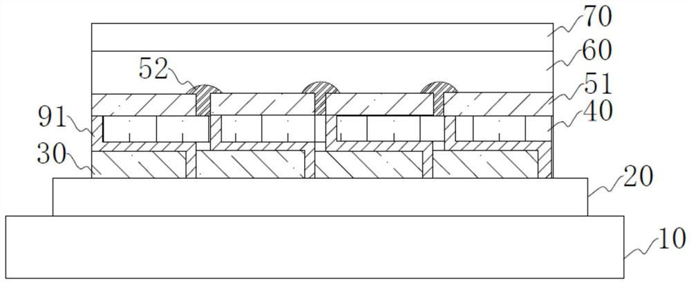
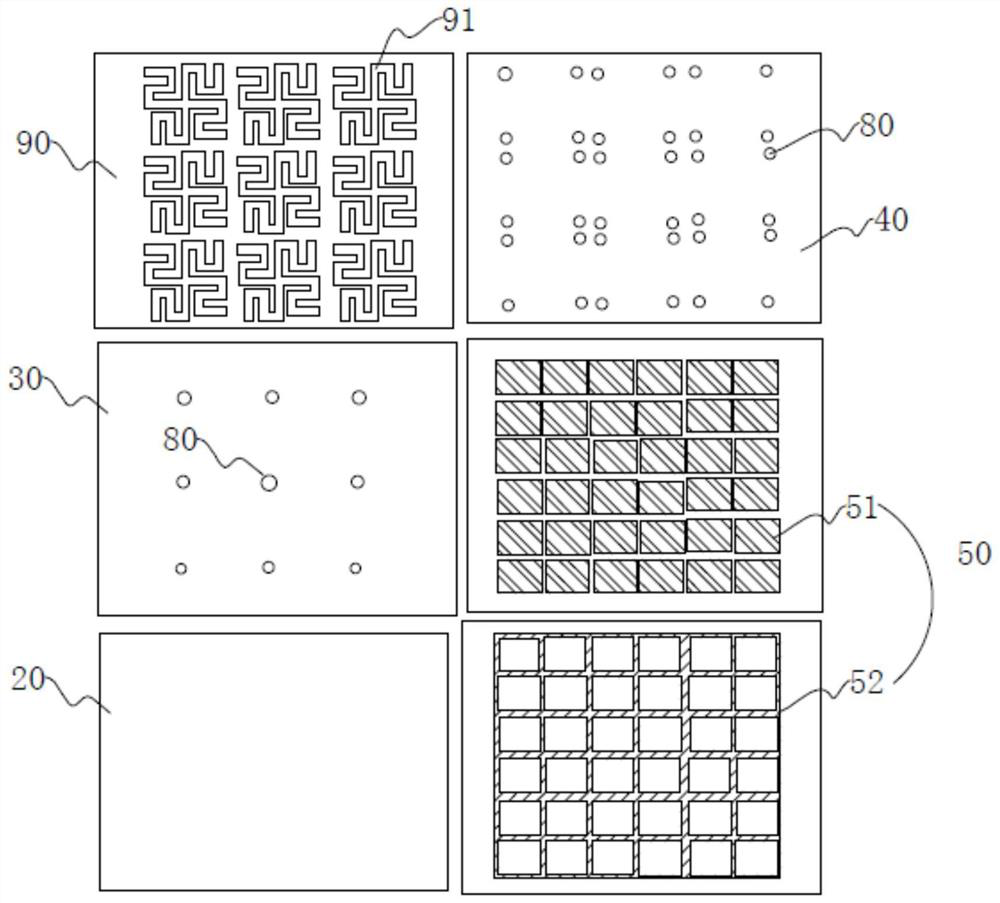
[0063] like Figure 4 and Figure 5 As shown, on the basis of Embodiment 1, the anti-short circuit structure layer 90 in this embodiment also includes a number of dimming areas 92 that are not in contact with the circuit protection device 91, that is, the dimming areas 92 and the The circuit protection device 91 is non-conductive; the thickness of the dimming area 92 is not uniform, for example, the dimming area 92 can be hill-shaped, saw-toothed or wave-shaped, etc., and the thickness at the highest point is 200um. In the embodiment, its thickness can also be other values ​​in the range of 20nm to 300um.

[0064] The bottom surface of the dimming area can be, for example, a circle, a square, or other regular or irregular shapes.

[0065] The dimming area can be achieved by patterning design with homogeneous materials with the circuit protection device, for example, both are made of indium tin oxide; it can also be achieved by coating with heterogeneous materials such as sca...

Embodiment 3

[0068] On the basis of Embodiment 1, the anti-short circuit structure layer 90 in this embodiment also includes several dimming areas that are not in contact with the circuit protection device 91, that is, the dimming areas are not in contact with the circuit protection device 91. Conductive; the dimming area is composed of transparent resin mixed with high refractive index scattering particles (such as titanium dioxide or zirconia nanometers), or composed of transparent resin mixed with micro lenses to form an optical scattering junction; the maximum thickness of the dimming area 30um, and the insulating area of ​​the second insulating layer evenly covers the dimming area and the circuit protection device to ensure that the dimming area does not have any contact with the pixel 51, and to ensure that the part of the circuit protection device that passes through the through hole 80 is in contact with the pixel 51 Except for the contact, other parts are not in contact with the pi...


PUM

PropertyMeasurementUnit
thicknessaaaaaaaaaa
thicknessaaaaaaaaaa
electrical resistanceaaaaaaaaaa

Abstract

The present application discloses an organic light-emitting device, comprising: a substrate; a conductive layer located on one side of the substrate; a first electrode, the first electrode is composed of several pixels, and insulating wrapping is provided between the pixels; The second electrode; at least one organic material layer arranged between the first electrode and the second electrode; at least two insulating layers arranged between the conductive layer and the first electrode, and through holes are opened on the insulating layer; arranged on the insulating layer An anti-short circuit structure layer between the layers, the anti-short circuit structure layer includes a plurality of circuit protection devices with the same electrical conduction characteristics; the circuit protection devices pass through the through holes and electrically connect the pixels of the first electrode with the conductive layer. The technical solution of the present application realizes ultra-high anti-short circuit resistance, improves the aperture ratio of the light-emitting area of ​​the organic light-emitting device, and improves the service life and performance of the organic light-emitting device as a whole.

Description

technical field [0001] The present disclosure generally relates to the field of organic photoelectric technology, and specifically relates to an organic light emitting device. Background technique [0002] The organic light-emitting phenomenon refers to a phenomenon in which electrical energy is converted into light energy by using an organic material. Devices made using this principle are called organic light-emitting devices, such as OLEDs, QLEDs, and PLEDs. The principle of light-emitting OLEDs is that an organic material is placed between the cathode and the anode. When a voltage is applied between the anode and the cathode, The anode injects holes into the organic material, and the cathode injects electrons into the organic material layer. The holes and electrons injected into the organic material layer combine to generate excitons, which emit light when they migrate to the ground state. [0003] Dust particles, burrs, pinholes, cracks and other defects are inevitable...

Claims


Application Information

Patent Timeline
Patent Type & Authority Patents(China)
IPC IPC(8): H01L27/32
CPCH10K59/123H10K59/124H10K59/1315
Inventor 李育豪朱映光谢静张国辉胡永岚
Owner GUAN YEOLIGHT TECH CO LTD
Why Eureka
Try Eureka