Anti-blocking floor drain

A floor drain and filter element technology, which is applied in the field of bathroom floor drains, can solve the problems of affecting the rotation of fan blades, failure to reset, and affecting normal use, etc., and achieves the effects of low processing accuracy, long service life, and stable work

Active Publication Date: 2019-07-30
台州道业科技有限公司
View PDF9 Cites 7 Cited by
  • Summary
  • Abstract
  • Description
  • Claims
  • Application Information

AI Technical Summary

Problems solved by technology

[0004] 2. Hair is easily entangled on the upper and lower positioning shafts of the double-edged impeller, which affects its use effect and service life
[0006] 1. As mentioned above, the hair is easily entangled on the fan blades and movable sleeve, which affects its use effect and service life
[0007] 2. It cannot be automatically reset after cutting, so that the main drain hole and the auxiliary drain hole are aligned every ti

Method used


Image

  • Anti-blocking floor drain
  • Anti-blocking floor drain
  • Anti-blocking floor drain

Examples


Example Embodiment

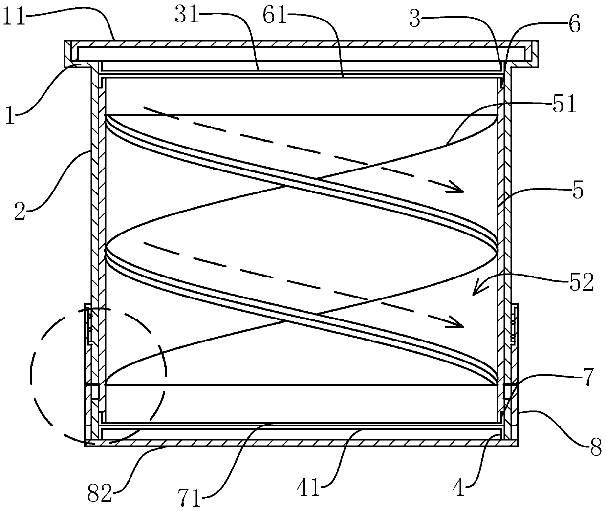
[0046] Embodiment one: if Figure 1-4 As shown, an anti-blocking floor drain of the present invention includes a cylindrical filter cartridge 2 with a filter seat 1 fixed on the top, a detachable cover on the filter seat 1 with a filter cover 11 for decoration, and a cylindrical filter cartridge 2 is arranged inside the filter cartridge 2 Shaped filter core 5, the filter core 5 is fixed with a rotary plate 51, the rotary plate 51 is a spiral plate structure around the axis of the filter core 5, and the outer side of the rotary plate 51 is a spiral structure, and is fixed with the inner wall of the filter core 5, and the filter core 5 passes through the rotary The plate 51 separates to form a double-helical water outlet channel 52, and also includes an annular upper grid ring 3 and a lower grid ring 4 that are respectively located at the upper and lower ends of the filter element 5 and are coaxially fixed with the inner wall of the filter cartridge 2. The upper and lower ends of...

Example Embodiment

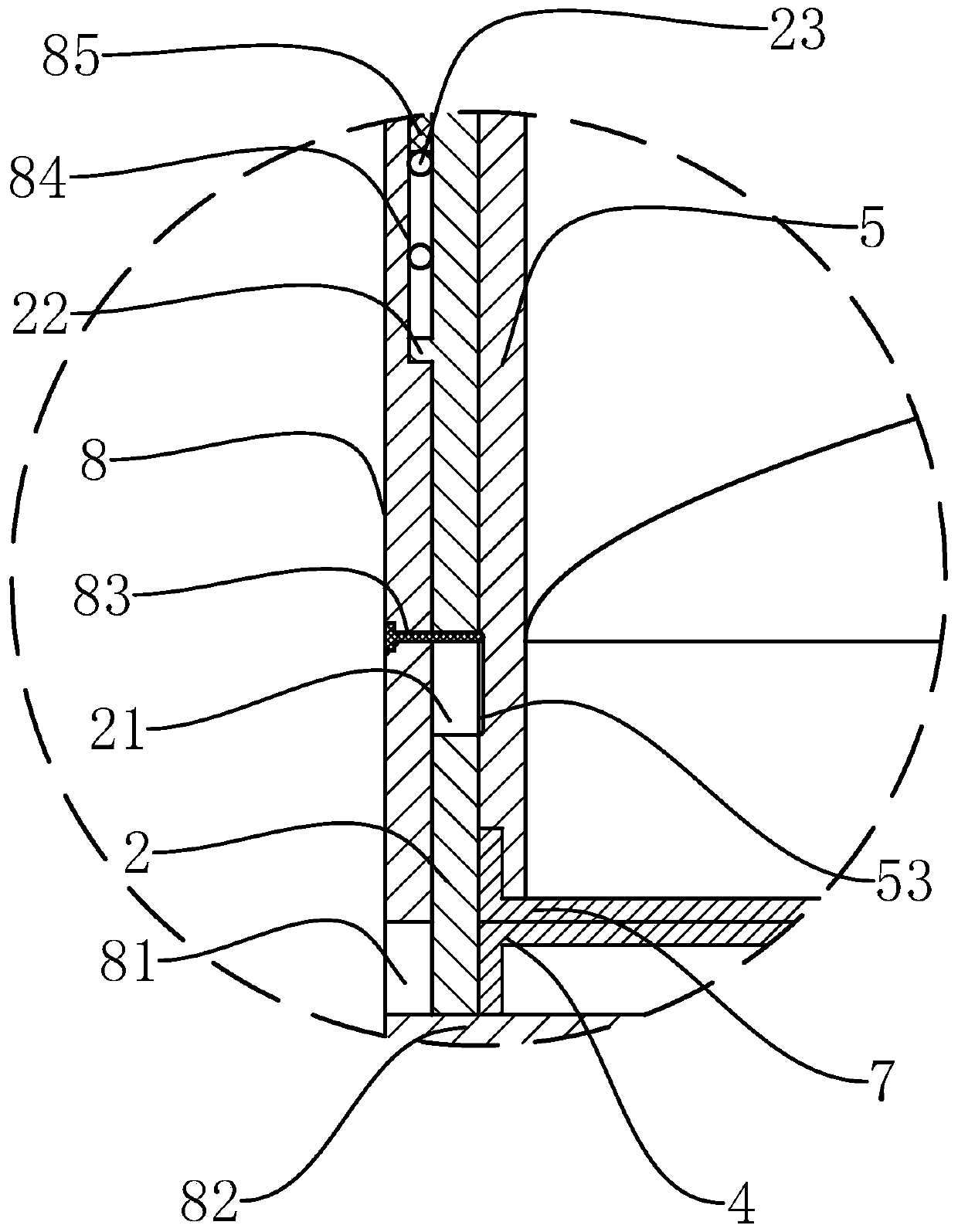
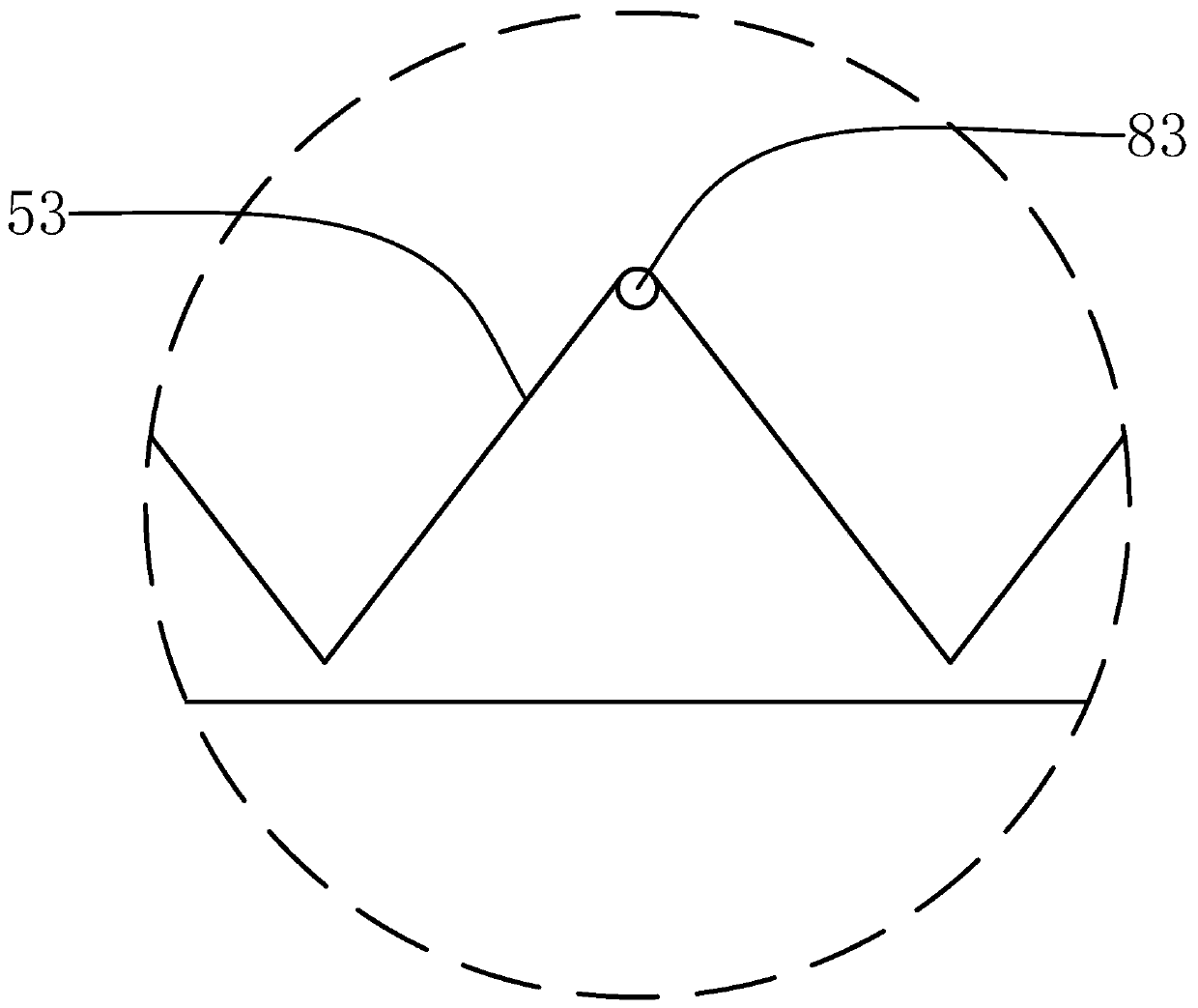
[0051] Embodiment 2: This embodiment is basically the same as Embodiment 1, the difference is that, as Figure 4-6 As shown, the reset mechanism includes an annular reset groove 2 54 coaxially located on the outer wall of the filter core 5. The bottom of the reset groove 54 is a regular wave-shaped structure around the axis of the filter core 5, and the deepest part of the reset groove 2 54 is a trough, and the trough The number is the same as that of the upper grid bars 31. The reset mechanism also includes a rod groove 24 located on the inner wall of the filter cartridge 2 and arranged radially along the filter cartridge 2. It also includes a reset rod 26 and a reset spring 2 that are movable in the rod groove 24. 25. The two ends of the reset spring 25 respectively offset the rear end of the reset rod 26 and the rod groove 24, and push the reset rod 26, so that the front end of the reset rod 26 slides in the reset groove 2 54, and is located in any of the reset groove 2 54 ...


PUM


Abstract

The invention provides an anti-blocking floor drain, and belongs to the field of bathroom accessory floor drains. According to the anti-blocking floor drain, the problems of poor hair cutting efficiency and structural instability are solved. The anti-blocking floor drain comprises a filter cylinder, wherein a filter seat is fixed to the top end of the filter cylinder, the filter cylinder is internally provided with a filter element, the filter element is internally provided with a spiral plate-shaped rotating plate, the anti-blocking floor drain further comprises an upper grid ring and a lowergrid ring, wherein the upper grid ring and the lower grid ring are respectively located at the upper end and the lower end of the filter element and fixed to the inner wall of the filter cylinder, acircular upper knife ring and lower knife ring are fixed to the upper end and the lower end of the filer element, the bottom surface of the upper grid ring and the top surface of the lower grid ring attached to the top surface of the upper knife ring and the bottom surface of the lower knife ring respectively, the upper grid ring and the lower grid ring are respectively provided with a plurality of upper grid bars and lower grid bars, the upper grid bars and the lower grid bars are spiral structures, the upper knife ring and the lower knife ring are provided with an upper knife blade and a lower knife blade, the shapes of the upper knife blade and the lower knife blade areas the same as the shapes of the upper grid bars and the lower grid bars, and the upper knife blade and the lower knifeblade are provided with sharp knife edges in the length direction. According to the anti-blocking floor drain, hair or debris can be cut off conveniently, and the structure is very stable.

Description

technical field [0001] The invention belongs to the technical field of bathroom floor drains, and relates to an anti-blocking floor drain. Background technique [0002] Existing floor drains generally can only filter part of the hair, and a large amount of hair will flow down into the sewer pipe through the leak hole, and it is easy to be wound into a ball and block the sewer pipe; Chinese invention patent, which sets a double-edged impeller in the floor drain, and uses the double-edged impeller to closely fit the radial grille of the filter grate and the radial grille of the intermediate grate, forming a scissors effect, and cutting off debris or hair to avoid debris Or the hair blocks the downpipe, while eliminating the need to clean up the sundries, but it has the following problems: [0003] 1. Since the hair is thin and easily entangled on the grille, the upper blade of the impeller and the lower blade of the impeller on the double-edged impeller must cooperate closely...

Claims


Application Information

Patent Timeline
IPC IPC(8): E03F5/04
CPCE03F5/0407E03F5/041
Inventor 林玉平
Owner 台州道业科技有限公司
Why Eureka
Try Eureka