
Method for manufacturing detachable modular tread for concrete casting
A manufacturing method and dismantling technology, which are applied in the directions of construction, building structure, scaffolding accessories, etc., can solve the problems of unfavorable personal carrying, difficulty in passing, difficulty in erection, etc., and achieve convenient transportation and transition, light weight, and avoid direct footing. The effect of stepping on steel bars and pre-buried pipes
Patent Information
- Authority / Receiving Office
- CN · China
- Current Assignee / Owner
- Publication Date
- 2019-07-30
- Estimated Expiration
- Not applicable · inactive patent
Smart Images
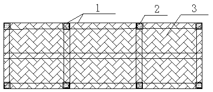
Figure 1 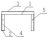
Figure 2 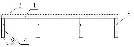
Figure 3
Abstract
Description
technical field
[0001] The invention relates to an auxiliary tool for replacing a springboard in concrete pouring, in particular to a method for manufacturing a detachable modular pedal for concrete pouring. Background technique
[0002] In the process of concrete pouring, the problem of disturbance and damage to steel bars and pre-embedded pipelines often occurs. Usually, measures such as laying springboards are used in actual construction to avoid damage to steel bars and pre-embedded pipelines. However, there are many disadvantages of the springboard, which usually have the following types: heavy, which is not conducive to personal carrying; long, difficult to pass through corners such as stairs; narrow, difficult to set up, and operators cannot stand stably during construction.
[0003] Therefore measures such as making the springboard of construction auxiliary tool in the known pouring of concrete exist above-mentioned various inconveniences and problems. Contents of...
Examples
Embodiment 1
[0035] The manufacturing method of the detachable modular pedal for concrete pouring of the present invention comprises the following steps:
[0036] a. Set up a rectangular frame,
[0037] see now Figure 1-Figure 3 , figure 1 It is a schematic structural diagram of a pedal rectangular frame according to an embodiment of the present invention, figure 2 for figure 1 side view, image 3 for figure 1 main view. As shown in the figure, use the first angle steel 1 to build a rectangular frame with a length of 1800 mm and a width of 600 mm; inside the rectangular frame, the longitudinal rails and cross rails arranged in the shape of "Feng" are welded to form three longitudinal rails and rails with the same distribution spacing. Four crossbars with the same spacing, the distance between two adjacent crossbars is 600mm. The specification of the first angle steel is L50*50*5 angle steel.
[0038] b. Laying grid steel plate
[0039] Lay the grid steel plate 3 on the top surfa...