Bus waiting station with rainwater collection function

A technology for rainwater collection and bus stops, applied in the field of municipal engineering, can solve problems such as respiratory problems, poor air circulation, single structure and function, etc., to increase the contact area of ​​rainwater, increase the filtration speed, and rationally use water resources Effect

Inactive Publication Date: 2019-07-30
江苏佳宇科技有限公司
View PDF0 Cites 1 Cited by
  • Summary
  • Abstract
  • Description
  • Claims
  • Application Information

AI Technical Summary

Problems solved by technology

Through collection-water delivery-purification-storage and other channels, rainwater is accumulated and utilized to provide rainwater replenishment for greening, landscape water bodies, washing and groundwater sources, so as to achieve the purpose of comprehensive utilization of rainwater resources and water conservation. Now the waiting bus platform has It has become an indispensable and important part of the city. The existing bus stops have a single structure and function. They simply provide places for people to wait for buses. There is no development of other functions based on the number of waiting bus stops and the physical structure, such as rainwater collection. Some bus stops do not take rainwater collection and utilization into consideration. Individual waiting bus stops are equipped with rainwater collection devices, but they cannot make good use of the collected rainwater, nor can they be purified and filtered. The poor air circulation at the waiting bus platform can easily lead to respiratory problems

Method used


Image

  • Bus waiting station with rainwater collection function
  • Bus waiting station with rainwater collection function
  • Bus waiting station with rainwater collection function

Examples


Embodiment Construction

[0022] The following will clearly and completely describe the technical solutions in the embodiments of the present invention with reference to the accompanying drawings in the embodiments of the present invention. Obviously, the described embodiments are only some, not all, embodiments of the present invention. Based on the embodiments of the present invention, all other embodiments obtained by persons of ordinary skill in the art without making creative efforts belong to the protection scope of the present invention.

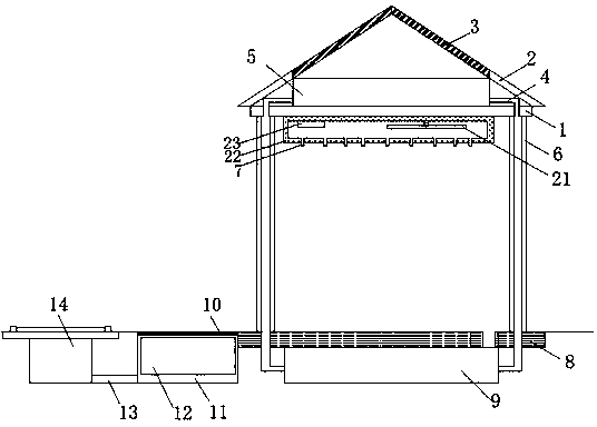
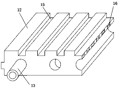
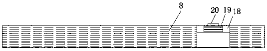
[0023] Embodiments of the present invention provide a waiting bus platform with rainwater collection function, such as Figure 1-4 As shown, including the top plate 1, the top of the top plate 1 is fixedly installed with the first water storage tank 5, the left and right sides of the top of the top plate 1 are fixedly connected with the diversion baffle 2, and the upper surface of the diversion baffle 2 is provided with a drip line 17. The end of the diversion...


PUM


Abstract

The invention provides a bus waiting station with a rainwater collection function. The bus waiting station with the rainwater collection function comprises a top plate, wherein a first water storage tank is fixedly arranged at the top of the top plate; flow-guiding baffles are fixedly connected to the left side and the right side of the top of the top plate; the ends, away from the top plate, of the flow-guiding baffles are fixedly connected with two first filter plates; and stand columns are fixedly arranged at the bottom of the top plate. According to the bus waiting station with the rainwater collection function, and the ends, connected with each other, of the two first filter plates are inclined upwards, so that the rainwater contact area and the filtering speed are increased; rainwater drips into the first water storage tank after being filtered by the first filter plates; the left side and the right side of the first water storage tank are fixedly connected with water delivery pipes; and the ends, away from the first water storage tank, of the water delivery pipes sequentially penetrate through the top plate, the stand columns and a base and are fixedly connected with a second water storage tank, so that the physical structure of the bus waiting station is reasonably utilized through the arrangement, the rainwater collection function is developed, and water resources arereasonably utilized.

Description

technical field [0001] The invention relates to the technical field of municipal engineering, in particular to a waiting bus stop with the function of collecting rainwater. Background technique [0002] The rainwater harvesting system, in a complete sense, should be called "rainwater harvesting and utilization system", which refers to the collection and utilization of rainfall runoff collected from hardened surfaces such as building roofs, roads, and squares. Through collection-water delivery-purification-storage and other channels, rainwater is accumulated and utilized to provide rainwater replenishment for greening, landscape water bodies, washing and groundwater sources, so as to achieve the purpose of comprehensive utilization of rainwater resources and water conservation. Now the waiting bus platform has It has become an indispensable and important part of the city. The existing bus stops have a single structure and function. They simply provide places for people to wai...

Claims


Application Information

Patent Timeline
Patent Type & Authority Applications(China)
IPC IPC(8): E04H1/12E03B3/02E03B11/00E04D13/04E03F5/10E03F5/14F24F7/007
CPCE03B3/02E03B11/00E03F5/10E03F5/14E04D13/04E04H1/1211F24F7/007Y02A20/108
Inventor 张滨倪恒王永辉郭靖季华明沈萌
Owner 江苏佳宇科技有限公司
Why Eureka
Try Eureka