
Display panel and manufacturing method thereof

A technology for a display panel and a manufacturing method, which is used in the manufacture of semiconductor/solid-state devices, electrical components, and electrical solid-state devices, etc., can solve problems such as residues on the second inorganic insulating layer, and prevent the risk of stress concentration or film peeling. The effect of improving product yield

Active Publication Date: 2019-07-30
WUHAN CHINA STAR OPTOELECTRONICS SEMICON DISPLAY TECH CO LTD
View PDF3 Cites 9 Cited by
  • Summary
  • Abstract
  • Description
  • Claims
  • Application Information

AI Technical Summary

Problems solved by technology

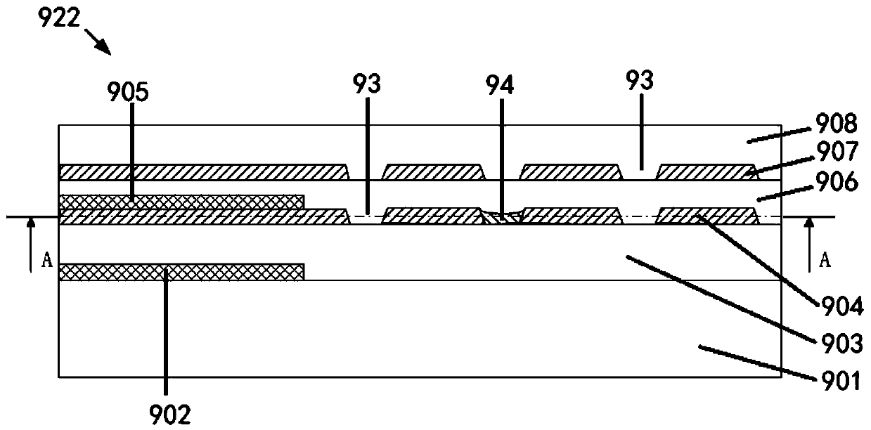
[0006] The purpose of the present invention is to provide a display panel and its manufacturing method to solve the problem in the prior art that the residue of the second inorganic insulating layer is generated at the through hole of the first signal line

Method used


Image

  • Display panel and manufacturing method thereof
  • Display panel and manufacturing method thereof
  • Display panel and manufacturing method thereof

Examples


Embodiment Construction

[0047]In describing the present invention, it should be understood that the terms "center", "longitudinal", "transverse", "length", "width", "thickness", "upper", "lower", "front", " Orientation indicated by rear, left, right, vertical, horizontal, top, bottom, inside, outside, clockwise, counterclockwise, etc. The positional relationship is based on the orientation or positional relationship shown in the drawings, which is only for the convenience of describing the present invention and simplifying the description, rather than indicating or implying that the referred device or element must have a specific orientation, be constructed and operated in a specific orientation, Therefore, it should not be construed as limiting the invention. In addition, the terms "first" and "second" are used for descriptive purposes only, and cannot be interpreted as indicating or implying relative importance or implicitly specifying the quantity of indicated technical features. Thus, a feature ...


PUM


Abstract

The invention provides a display panel and a manufacturing method thereof. A display area and a bending area are defined on the display panel, the display panel comprises a flexible substrate, a firstinorganic insulating layer, a first organic insulating layer, a first metal layer, a second organic insulating layer, a second inorganic insulating layer, a second metal layer and a third organic insulating layer which are arranged in a stacking mode. The manufacturing method of the display panel comprises the following steps of: providing a flexible substrate, manufacturing a first inorganic insulating layer, manufacturing a first organic insulating layer, manufacturing a first metal layer, manufacturing a second organic insulating layer, manufacturing a second inorganic insulating layer, manufacturing a second metal layer and manufacturing a third organic insulating layer. According to the invention, the second inorganic insulating layer of the bending area is arranged on the second organic insulating layer, so that residues of the second inorganic insulating layer generated in the through holes of the first metal layer are avoided, the risk of stress concentration or film peeling generated by a first signal line under bending stress is avoided, and the product yield is improved.

Description

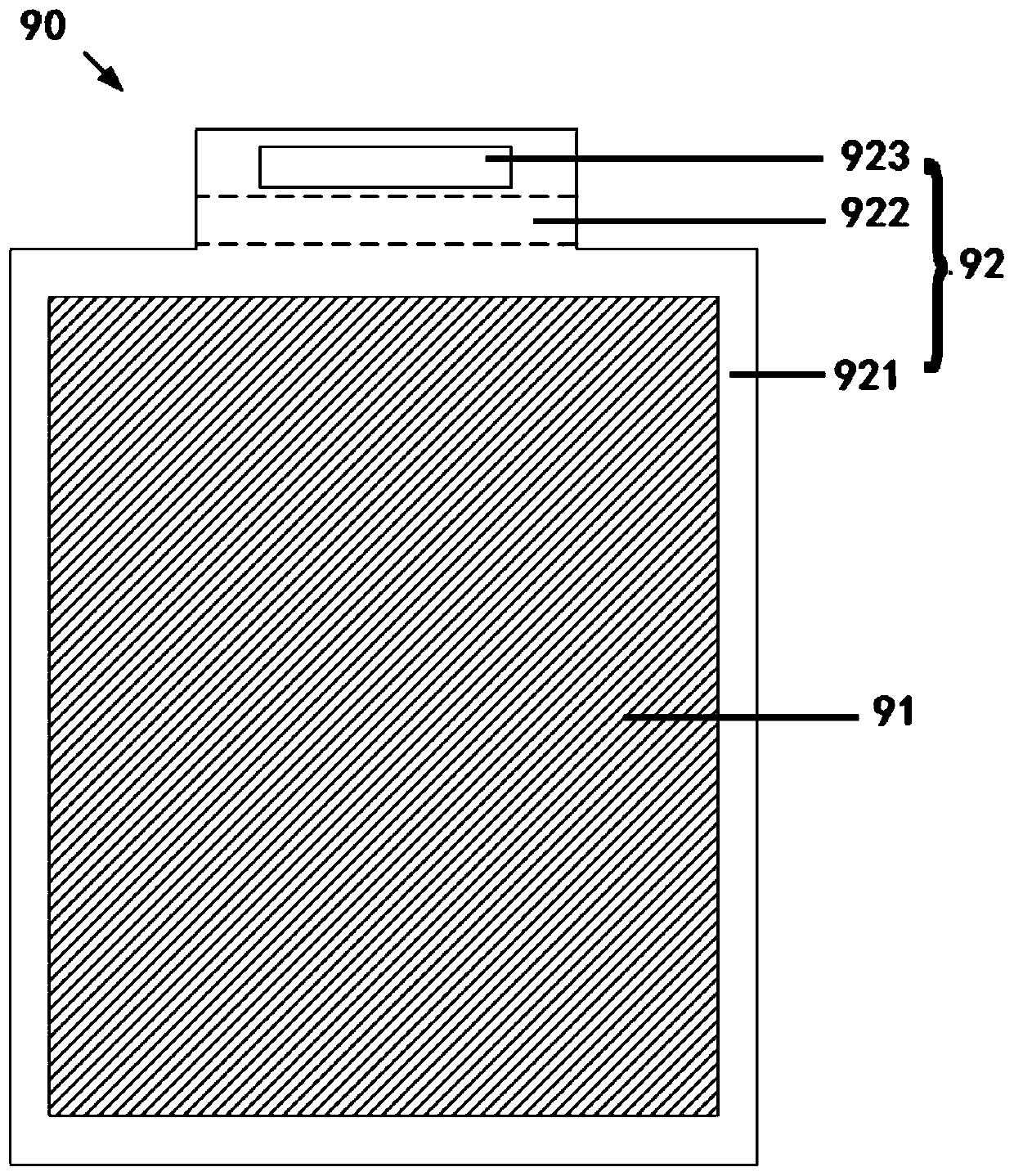
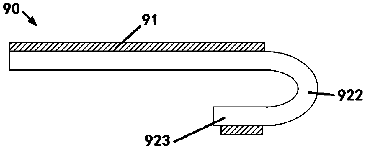
technical field [0001] The invention relates to the display field, in particular to a display panel and a manufacturing method thereof. Background technique [0002] Such as figure 1 , figure 2 As shown, it is a schematic diagram of the planar structure and cross-sectional structure of the existing flexible display panel. The flexible display panel 90 includes a display area 91 and a non-display area 92. The non-display area 92 includes a peripheral area 921 surrounding the display area 91, a bending area 922 and Circuit board area 923 . The flexible display panel 90 usually adopts a soft and bendable plastic substrate, which is suitable for manufacturing narrow-frame display devices. The flexible display panel 90 designs a bending area 922 in the peripheral signal routing area, so that the signal routing area and the circuit board area 923 are folded and placed on the side or below the flexible display panel 90, thereby reducing the occupation of the non-display area 92...

Claims


Application Information

Patent Timeline
Patent Type & Authority Applications(China)
IPC IPC(8): H01L27/12H01L21/77
CPCH01L27/1218H01L27/1248H01L27/1262
Inventor 余佩
Owner WUHAN CHINA STAR OPTOELECTRONICS SEMICON DISPLAY TECH CO LTD
Learn More