Battery unit for vehicle

A technology for battery cells and vehicles, applied in batteries, electrical components, secondary batteries, etc., to reduce manufacturing costs and avoid radio wave interference

Active Publication Date: 2019-07-30
HONDA MOTOR CO LTD
View PDF17 Cites 3 Cited by
  • Summary
  • Abstract
  • Description
  • Claims
  • Application Information

AI Technical Summary

Problems solved by technology

[0006] However, the countermeasure described in Patent Document 1 is a countermeasure for blocking electrical noise to the

Method used


Image

  • Battery unit for vehicle
  • Battery unit for vehicle
  • Battery unit for vehicle

Examples


Embodiment Construction

[0048] Hereinafter, a vehicle battery unit (hereinafter referred to as a battery unit) according to an embodiment of the present invention will be described with reference to the drawings. figure 1 A system configuration diagram of a vehicle equipped with a battery unit according to an embodiment of the present invention will be described. exist Figure 1 to Figure 7 In , the front of the battery cell is shown as Fr, the rear is shown as Rr, the left side is shown as L, the right side is shown as R, the upper side is shown as U, and the lower side is shown as D.

[0049] The vehicle V mounts a battery unit 10 under the floor. In the vehicle V, high-voltage units P1 and P2 are provided front and rear with the battery unit 10 interposed therebetween, and a motor MOT that receives electric power from the battery unit 10 to drive rear wheels is arranged at the rear of the vehicle V.

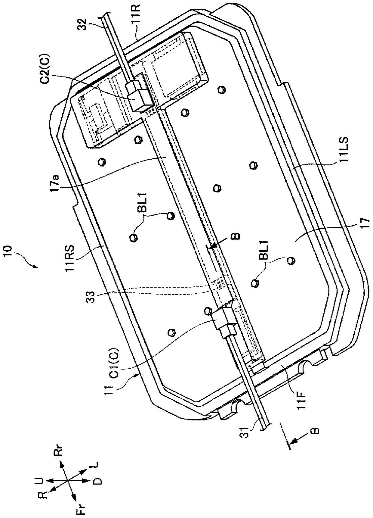
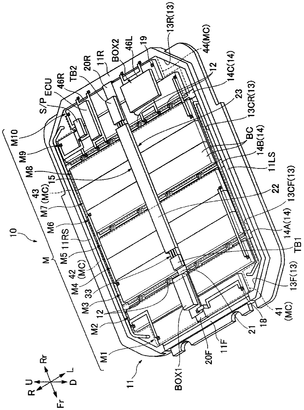
[0050] Such as figure 2 and image 3 As shown, the battery unit 10 includes: a battery modul...


PUM


Abstract

The present invention provides a battery unit for a vehicle which can avoid the interference of electric wave generated to the outside and the inside of a battery shell due to the electric noise of acable. The battery unit for the vehicle (10) is provided with: a battery module (M) formed by stacking a plurality of battery cells; a battery case (11) that houses the battery module (M); a connectorsection (C) arranged in the battery case (11); and a cable (33) that electrically connects the connector section (C) and the battery module (M). The battery case (11) is provided with a metal frame beam (15) having a hollow section (25). The cable (33) is disposed in the hollow section (25) of the frame beam (15).

Description

technical field [0001] The present invention relates to a vehicle battery unit mounted on a vehicle. Background technique [0002] A battery unit mounted on a vehicle is provided with a cable that electrically connects a battery module formed by stacking a plurality of battery cells to a connector portion provided on the battery unit. A cable through which a relatively large current flows may cause radio wave interference to electronic devices arranged around the cable due to electrical noise, and therefore it is necessary to take measures to prevent radio wave interference. As a countermeasure against radio wave interference, for example, use of shielded electric wires is mentioned. [0003] However, since the shielded wire is expensive, the cost of the battery unit increases. In addition, as a countermeasure against radio wave interference of a battery cell, for example, a countermeasure described in Patent Document 1 is known (for example, Patent Document 1). [0004] ...

Claims


Application Information

Patent Timeline
IPC IPC(8): H01M2/10H01M2/20H01M10/42H01M10/48H01M10/613H01M10/625H01M10/655H01M10/6551H01M10/6556H01M10/6567B60K1/04
CPCH01M10/4207H01M10/425H01M10/482H01M10/613H01M10/625H01M10/655H01M10/6551H01M10/6556H01M10/6567B60K1/04H01M2220/20H01M50/20H01M50/50H01M50/502Y02E60/10
Inventor 坂本纮基远藤雄大川原诚片山亮关日出海
Owner HONDA MOTOR CO LTD
Why Eureka
Try Eureka