Charging circuit, charging method and a terminal

A charging circuit and charging method technology, applied in battery circuit devices, circuit devices, current collectors, etc., can solve problems such as loss of user data and charging failures in smart terminals.

Active Publication Date: 2019-07-30
东莞市榕品电子科技有限公司
View PDF7 Cites 2 Cited by
  • Summary
  • Abstract
  • Description
  • Claims
  • Application Information

AI Technical Summary

Problems solved by technology

[0003]At present, most smart devices are driven by the electric energy stored in their own batteries, and as the functions of smart terminals become more and more abundant, the power consumption of smart terminals The speed is also getting faster and faster, resulting in the need to frequently replenish power for smart terminals. As more and more personal information is stored in smart terminals, this information is becoming more and more important to users. At the same time, due to frequent Sexual charging can easily lead to charging failures in smart terminals. Therefore, there are more and more cases where charging failures occur on smart terminals, causing smart terminals to fail to turn on and resulting in loss of user data. Under such circumstances, it is very important to provide another charging method for smart terminals

Method used


Image

  • Charging circuit, charging method and a terminal
  • Charging circuit, charging method and a terminal
  • Charging circuit, charging method and a terminal

Examples


no. 1 example

[0057] In the Qualcomm mobile phone charging solution, the charging-related signals include VBUS, D+, D-, and GND signals. The charging speed is determined by the D+ and D- signals. Usually, the failure to charge is due to the abnormality of the D+ and D- lines (such as short circuit, impedance abnormality, abnormal common mode inductance, etc.), so the embodiment of the present invention adds a backup charging circuit on top of the normal D+, D- charging circuit, the backup charging circuit can be used when the normal D+, D- charging circuit cannot Temporarily charge the terminal when in use.

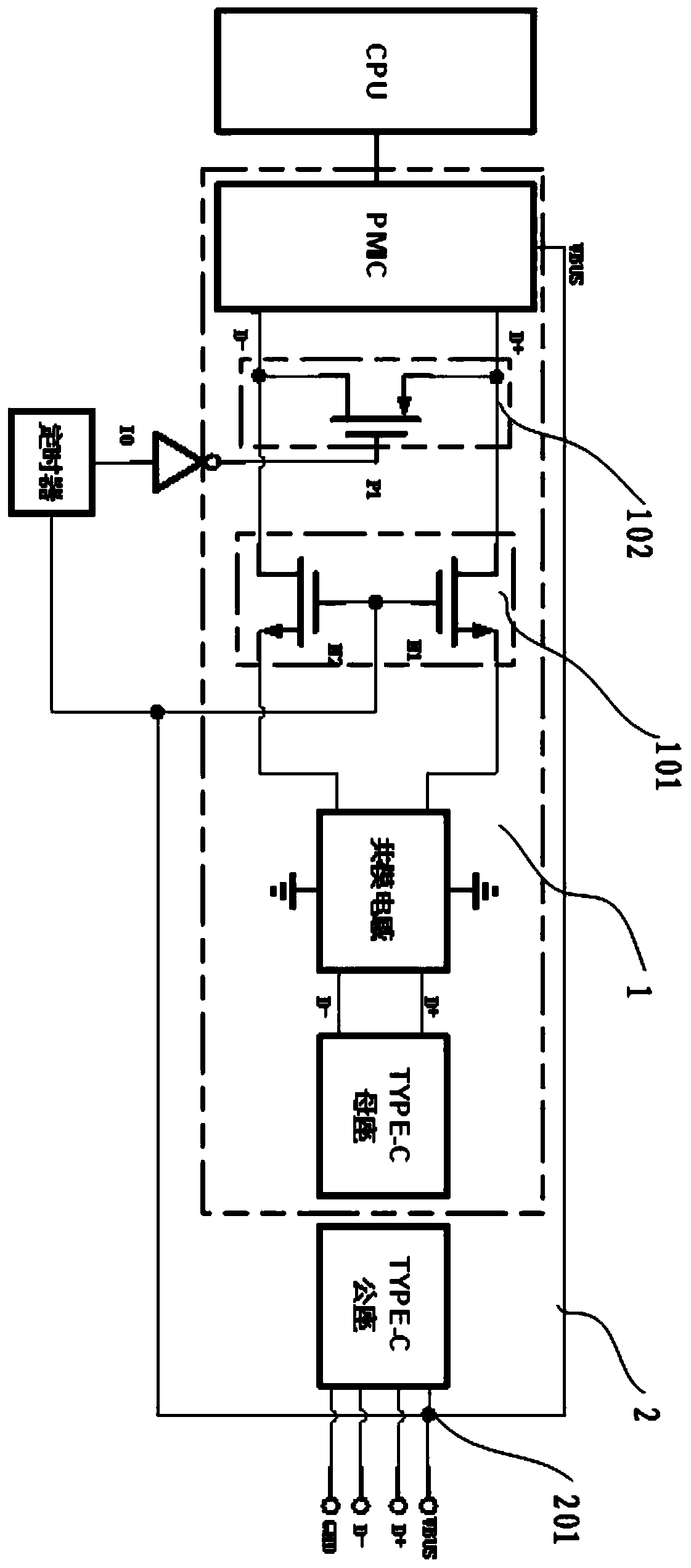
[0058] image 3 A schematic diagram of a charging circuit provided for this embodiment, the charging circuit is suitable for a terminal equipped with a Qualcomm charging solution, the charging circuit includes: a normal charging circuit 1 and a backup charging circuit 2; the normal charging circuit 1 consists of a USB socket, And from the D+ and D- pins of the USB female seat, the com...

no. 2 example

[0067] Figure 4 It is a flow chart of a charging method provided by the second embodiment of the present invention, the charging method includes:

[0068] S401. When charging starts, input a high potential to the VBUS contact of the backup charging circuit or leave it in the air.

[0069] In this embodiment, starting charging refers to inserting the USB male plug on the charger into the USB female plug on the terminal. In the Qualcomm mobile phone charging scheme, the signals related to charging include VBUS, D+, D-, and GND signals, so in On the charger and the terminal that support the Qualcomm charging solution, the VBUS, D+, D-, and GND signal pins all exist. When the USB male on the charger is inserted into the USB female on the terminal, the USB male and USB female The corresponding pins will be in contact for signal detection and power input.

[0070] S402. Detect whether the D+ and D- connecting lines in the normal charging circuit are normally conducted; when the D...

no. 3 example

[0083] This embodiment also provides a terminal, see Figure 5 As shown, the terminal includes a battery 51 and implements a proposed charging circuit 52 , wherein the battery 51 is charged by the charging circuit 52 .


PUM


Abstract

Embodiments of the invention provide a charging circuit, a charging method and a terminal. The charging circuit comprises a normal charging circuit and a standby charging circuit; the normal chargingcircuit is composed of a USB female base, and a common mode inductor, a first switch circuit, a second switch circuit and a charging management chip PMIC which are connected in sequence through a connecting line led out from D+ and D- pins of the USB female base; the standby charging circuit consists of a VBUS contact, a timer and a reverser I0; one end of the VBUS contact is connected with the charging management chip PMIC, and the other end of the VBUS contact comprises a first branch circuit and a second branch circuit; the first branch circuit is connected with the first switch circuit, and the second branch circuit is sequentially connected with the timer, the reverser I0 and the second switch circuit; and when the normal charging circuit breaks down, the VBUS contact of the standby charging circuit inputs a low level, so as to activate the standby charging circuit to charge the terminal, so that the problem that the terminal cannot be temporarily charged after a charging fault occurs in the normal charging circuit is solved.

Description

technical field [0001] The present invention relates to the technical field of charging terminals, and more specifically, to a charging circuit, a charging method and a terminal. Background technique [0002] With the popularization of various smart terminals such as smart phones, and the increasing integration of various smart terminals, the functions carried on smart terminals are becoming more and more abundant and powerful. With the improvement of social media, people have completed most of the video shooting and daily photo shooting through mobile phones. With the popularity of WeChat and other social software, people are also storing some important information on our smart phones. There are also smart wearable devices that are becoming more and more popular. These wearable devices can detect the user's physical condition by monitoring the user's daily activity and various physical signs. With the popularity of these smart devices, the important personal information sto...

Claims


Application Information

Patent Timeline
Patent Type & Authority Applications(China)
IPC IPC(8): H02J7/00
CPCH02J7/00
Inventor 范建功
Owner 东莞市榕品电子科技有限公司
Why Eureka
Try Eureka