Diatomite selecting throwing machine device

A technology of throwing machine and diatomite, which is applied in the direction of throwing machine, transportation and packaging, etc., can solve the problems of high temperature resistance, enterprise loss, diatomite quality is difficult to guarantee, etc., and achieve the effect of simple structure and improved quality

Pending Publication Date: 2019-08-02
王锡山
View PDF0 Cites 0 Cited by
  • Summary
  • Abstract
  • Description
  • Claims
  • Application Information

AI Technical Summary

Problems solved by technology

[0002] Diatomite can be processed into filter aids, fireproof boards, insulation materials, etc. During the processing of diatomite, a certain amount of strong acid and strong alkali materials will be added, and the drying temperature is several hundred degrees Celsius; diatomite materials It is obtained from diatomite ore through mining. After diatomite is mined, it needs further processing such as crushing and screening to obtain diatomite raw materials, but diatomite raw materials need to be transported during the screening process; the current diatomite Soil processing enterprises have used various equipment in the transportation of diatomite to no avail. The equipment is often eroded by the added strong acid and alkali, and the equipment materials are neither wear-resistant nor high-temperature resistant, resulting in frequent damage to the equipment. It makes it difficult to guarantee the quality of diatomite, and also greatly reduces the quality of diatomite materials, causing great losses to the enterprise.

Method used


Image

  • Diatomite selecting throwing machine device
  • Diatomite selecting throwing machine device
  • Diatomite selecting throwing machine device

Examples


Embodiment Construction

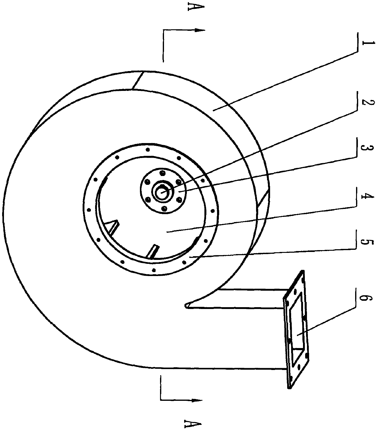
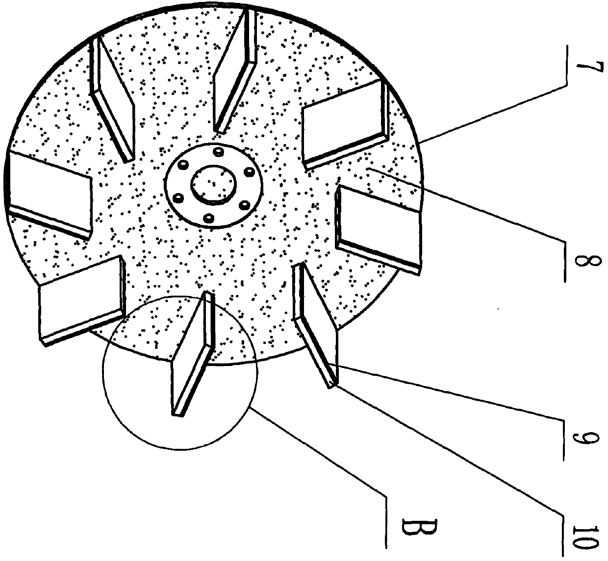
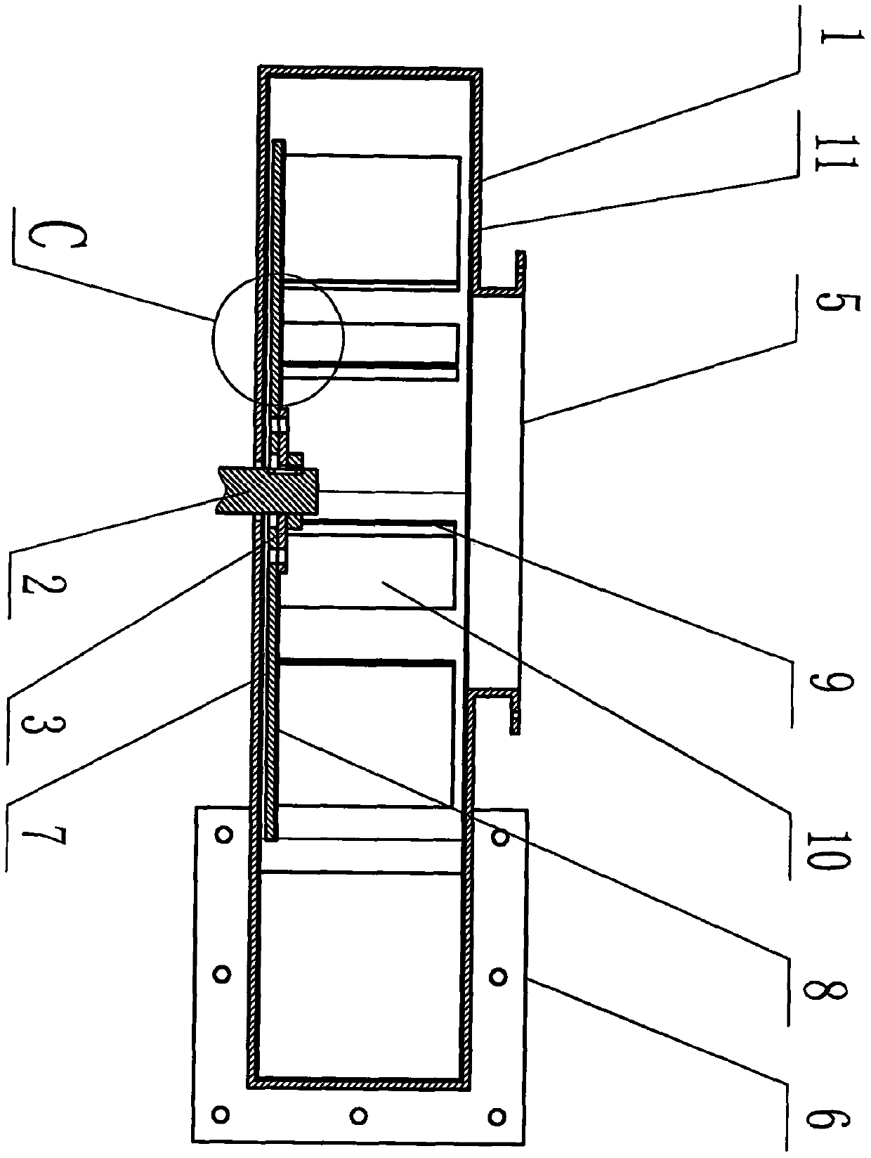
[0015] Refer to figure 1 , figure 2 , image 3 , Figure 4 , Figure 5 , The caster shell 1 is inlaid with a shell wear-resistant layer 11, the caster shell 1 is provided with an inlet 5 and an outlet 6, the caster wheel 4 is connected with the connecting piece 3, and the connecting piece 3 is connected with the The feeding wheel shaft 2 is connected by a key, and the throwing wheel 4 is assembled inside the shell 1 of the throwing machine. After the throwing wheel shaft 2 is powered, it can drive the throwing wheel 4 to rotate in the set direction; the throwing wheel main board 7 is connected to the throwing wheel. The main plate 10 constitutes the casting wheel 4, the main plate 7 of the casting wheel is inlaid with a wear-resistant layer 8 of the main plate, and the wear-resistant layer 9 of the casting plate is inlaid on the main plate 10; 8. The material of the wear-resistant layer 9 of the cast sheet is emery block or electroplated emery.


PUM


Abstract

The invention discloses a diatomite selecting throwing machine device. The diatomite selecting throwing machine device mainly comprises a throwing machine shell, a throwing wheel, a throwing wheel main plate, a main plate wear-resisting layer, a throwing piece wear-resisting layer, a throwing piece main plate and a shell wear-resisting layer, and is characterized in that the shell wear-resisting layer is inlaid on the throwing machine shell, the throwing wheel is connected with a connecting piece, the connecting piece is in key connection with a throwing wheel shaft, the throwing wheel is assembled inside the throwing machine shell, the main plate wear-resisting layer is inlaid on the throwing wheel main plate, and the throwing piece wear-resisting layer is inlaid on the throwing piece main plate. The throwing wheel shaft drives the throwing wheel to rotate in a set direction, diatomite materials are fed from a feeding port and then are discharged and thrown from a discharging port toa designated position, the shell wear-resisting layer, the main plate wear-resisting layer and the throwing piece wear-resisting layer are made of emery, the emery is resistant to strong acid, strongalkali and high temperature and is quite resistant to wear, so that the diatomite equipment is resistant to the strong acid, the strong alkali and the wear and is resistant to the high temperature even more, and then the equipment is not prone to damage.

Description

Technical field [0001] The invention relates to the technical field of diatomite processing equipment, in particular to a diatomite material selection and throwing machine device. Background technique [0002] Diatomaceous earth can be processed into filter aids, fireproof sheets, insulation materials, etc. A certain amount of strong acid and alkali materials are added during the process of diatomaceous earth processing, and the temperature during drying is several hundred degrees Celsius; diatomaceous earth materials It is obtained from diatomite ore after mining. After the diatomite is mined, it needs to be further crushed and screened to obtain the diatomite raw material, but the diatomite raw material needs to be transported during the screening process; the current diatomite Various equipment used by soil processing enterprises in the transportation of diatomite are not effective. The equipment is often corroded by the added strong acid and alkali, and the equipment material...

Claims


Application Information

Patent Timeline
IPC IPC(8): B65G31/04
CPCB65G31/04
Inventor 王锡山
Owner 王锡山
Why Eureka
Try Eureka