Textile thread residue removal equipment
A technology for textiles and thread ends, applied in the field of thread end removal equipment, can solve problems such as high labor intensity, people scratching, sharp edges of scrapers, etc., and achieve the effect of reducing labor intensity
- Summary
- Abstract
- Description
- Claims
- Application Information
AI Technical Summary
Problems solved by technology
Method used
Image

Examples
Embodiment 1
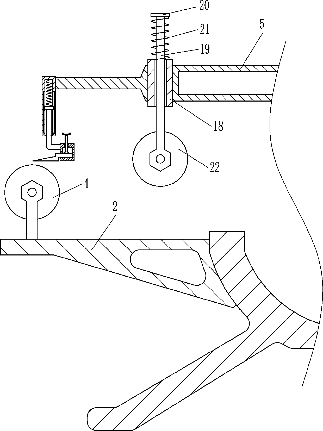
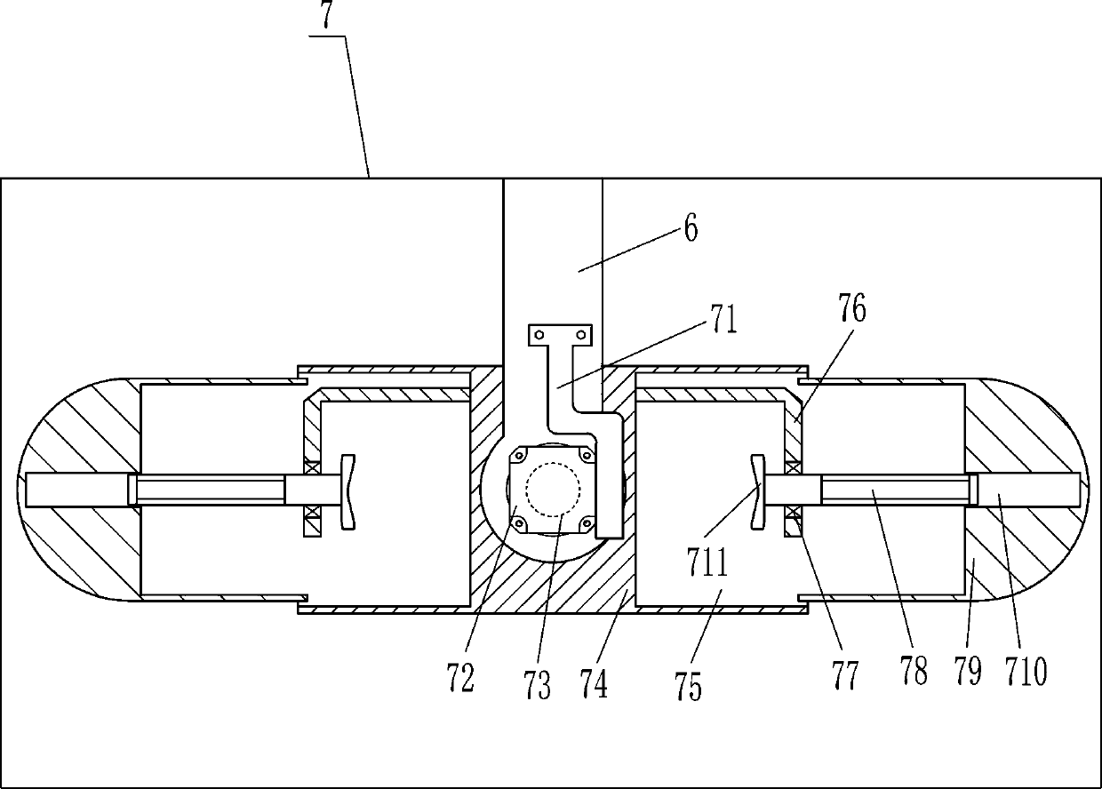
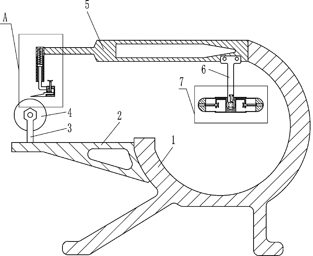
[0019] A textile thread removal device such as Figure 1-3 As shown, it includes a support 1, a first bracket 2, a first pole 3, a first roller 4, a second bracket 5, a first support plate 6, a collection device 7, a hollow tube 8, a slide rail 9, and a slider 10. The first spring 11, the third pole 12, the first fixed block 13, the first cutting blade 15 and the second screw rod 17, the first bracket 2 is fixed on the upper left side of the support 1, and the support 1 is passed through the bolt The way of connection is connected with the first support 2, the first support rod 3 is set on the left side of the top of the first support 2, the upper part of the first support rod 3 is connected with the first roller 4 which can guide the textile, and the second support 5 is fixed on the upper right side of the support 1, the second support 5 is connected to the support 1 through bolt connection, the first support plate 6 is fixed on the right side of the front side of the second ...
Embodiment 2
[0021] A textile thread removal device such as Figure 1-3 As shown, it includes a support 1, a first bracket 2, a first pole 3, a first roller 4, a second bracket 5, a first support plate 6, a collection device 7, a hollow tube 8, a slide rail 9, and a slider 10. The first spring 11, the third pole 12, the first fixed block 13, the first cutting blade 15 and the second screw 17, the upper left side of the support 1 is fixed with the first bracket 2, the first pole 3 Set on the left side of the top of the first support 2, the upper part of the first support rod 3 is rotatably connected with the first roller 4 that can guide the textile, the second support 5 is fixed on the upper right side of the support 1, the first support plate 6 is fixedly connected to the right part of the front side of the second bracket 5, and the collection device 7 that can wind textiles is installed on the lower part of the first support plate 6, and the hollow tube 8 is installed on the left side of...
Embodiment 3
[0024] A textile thread removal device such as Figure 1-4 As shown, it includes a support 1, a first bracket 2, a first pole 3, a first roller 4, a second bracket 5, a first support plate 6, a collection device 7, a hollow tube 8, a slide rail 9, and a slider 10. The first spring 11, the third pole 12, the first fixed block 13, the first cutting blade 15 and the second screw 17, the upper left side of the support 1 is fixed with the first bracket 2, the first pole 3 Set on the left side of the top of the first support 2, the upper part of the first support rod 3 is rotatably connected with the first roller 4 that can guide the textile, the second support 5 is fixed on the upper right side of the support 1, the first support plate 6 is fixedly connected to the right part of the front side of the second bracket 5, and the collection device 7 that can wind textiles is installed on the lower part of the first support plate 6, and the hollow tube 8 is installed on the left side of...
PUM
 Abstract
Description
Claims
Application Information
 - R&D
- Intellectual Property
- Life Sciences
- Materials
- Tech Scout
- Unparalleled Data Quality
- Higher Quality Content
- 60% Fewer Hallucinations
Browse by: Latest US Patents, China's latest patents, Technical Efficacy Thesaurus, Application Domain, Technology Topic, Popular Technical Reports.
© 2025 PatSnap. All rights reserved.Legal|Privacy policy|Modern Slavery Act Transparency Statement|Sitemap|About US| Contact US: help@patsnap.com