BOPP film winding device

A winding device and film technology, applied in the direction of winding strips, thin material processing, transportation and packaging, etc., can solve the problems of film deformation, unfavorable development, high cost, etc., and achieve the effect of avoiding loosening

Inactive Publication Date: 2019-04-12
安徽长正升科技有限公司
View PDF8 Cites 11 Cited by
  • Summary
  • Abstract
  • Description
  • Claims
  • Application Information

AI Technical Summary

Problems solved by technology

[0004] In order to ensure the winding of film semi-finished products at different speeds, the winding device needs a tension adjustment mechanism. In the BOPP film production line, the winding device of the extruder generally has the following two types. One is to use the mechanical structure to make the film winding drum However, due to the characteristics of thin film, easy to break and easy deformation, the winding of this kind of winding device can easily cause film breakage or film deformation; the other is electronic control, according to the state of the extruder , film output speed, temperature and other conditions to control the tension of the winding drum, but the cost of this control device is relatively high, which increases the production cost of the already expensive extruder, which is not conducive to the development of the industry
[0005] Moreover, in the existing film winding device, when the film winding is completed, the film is cut off manually to stop the continuous winding, which is time-consuming and labor-intensive, and the degree of automation is low; at the same time, the winding drum after winding cannot Guaranteed to have the same thickness

Method used


Image

  • BOPP film winding device
  • BOPP film winding device
  • BOPP film winding device

Examples


Embodiment 1

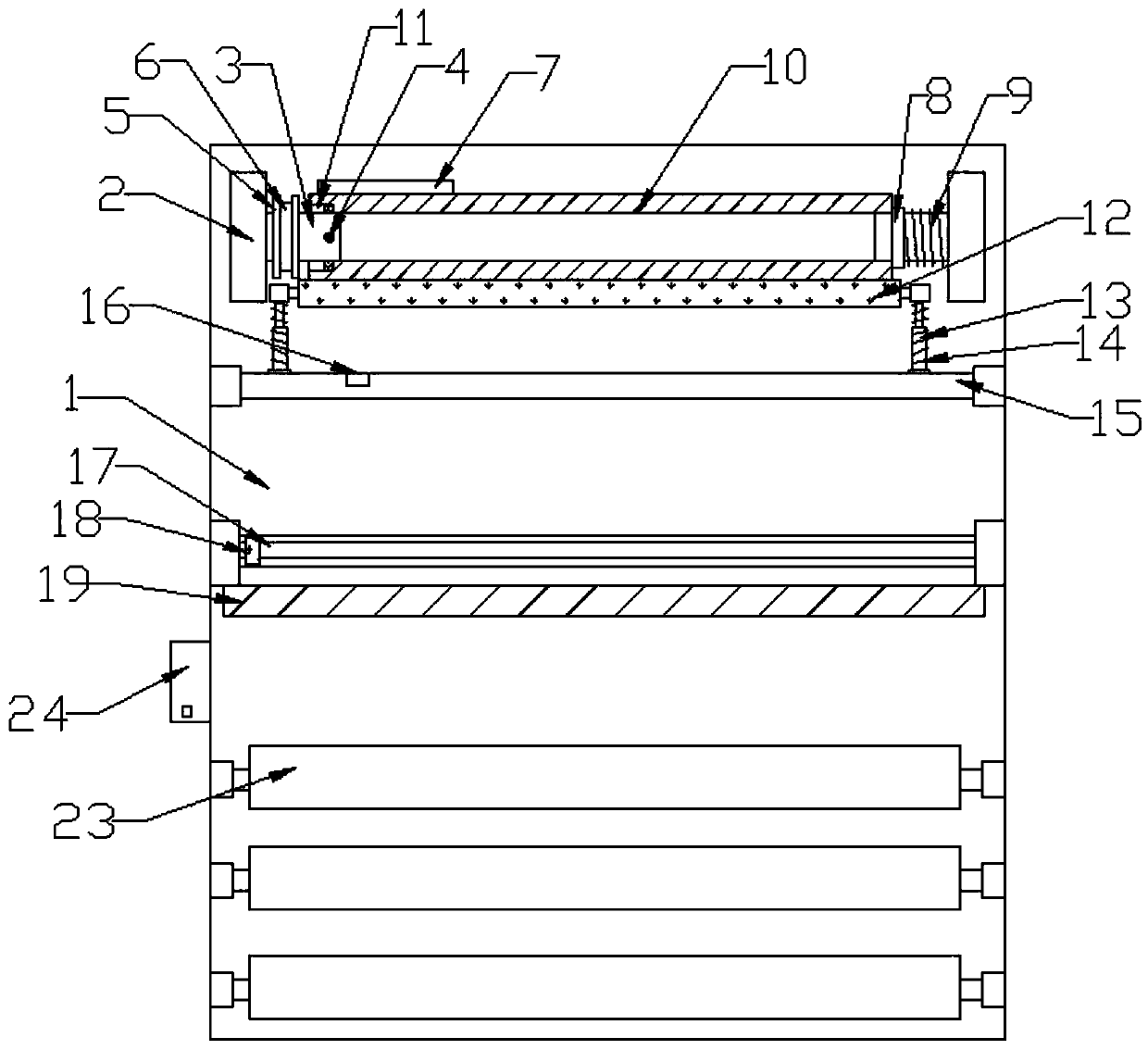
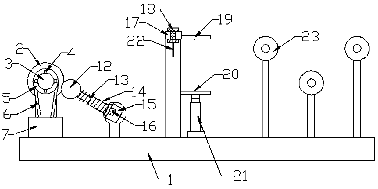
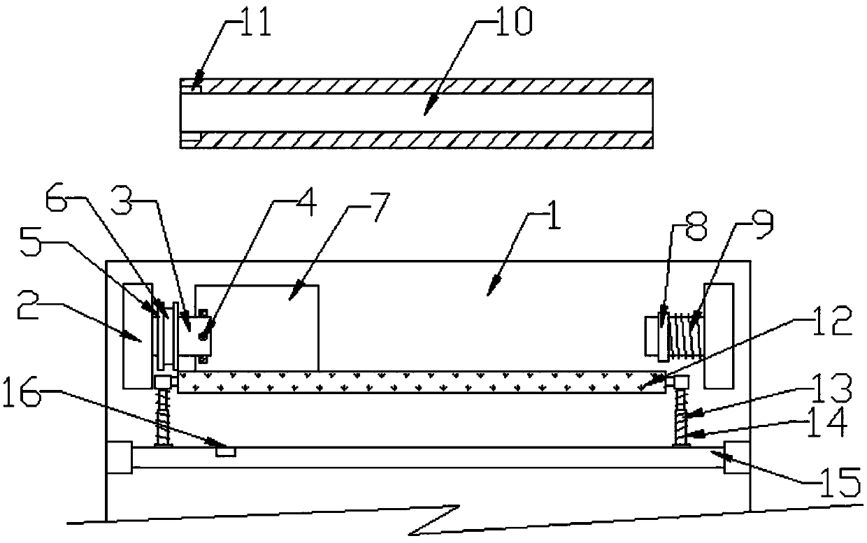
[0030] Such as Figure 1-5 As shown, a BOPP film winding device includes a worktable 1, a support frame 2, a winding mechanism, a pressing structure, a cutting mechanism, a control mechanism, and a receiving roller 23. The winding mechanism includes two fixed shafts 3, two A winding roller 10 is sleeved between the fixed shafts 3, and one of the fixed shafts 3 is connected to a rotating motor 7 through a pulley 5 and a belt 6. The pressing mechanism includes a pressing roller 12, and both ends of the pressing roller 12 are connected with telescopic The telescopic rod 13 of the spring 14 has a cutting mechanism including an electric slide rail 17, a fixed pressing plate 19 and a movable pressing plate 20, and the control mechanism is a control box 24.

[0031] A set of support frames 2 are welded symmetrically on the workbench 1. A set of fixed shafts 3 are installed on the inside of the support frame 2 through bearings. One of the fixed shafts 3 is equipped with a pulley 5, and t...

Embodiment 2

[0033] Such as Figure 1-5 As shown, the pressing roller 12 in the pressing mechanism is tightly attached to the bottom of one side of the winding roller 10. Both ends of the winding roller 12 are also threadedly connected with an inclined telescopic rod 13, and the telescopic rod 13 is sleeved with a telescopic spring 14. Through the elastic force of the telescopic spring 14, the pressure roller 12 is tightly attached to the winding roller 10, the telescopic rod 13 is mounted on the cross bar 15 through a bearing, and the cross rod 15 is welded to the workbench 1 through the support rod.

[0034] The two ends of the pressure roller 12 are respectively equipped with connecting blocks through bearings. The telescopic rod 13 is threadedly connected to the connecting block, and the telescopic rod 13 is also installed on the cross rod 15 through bearings to facilitate the connection between the telescopic rod 13 and the pressure roller 12 Separate, install or replace a telescopic spr...

Embodiment 3

[0037] Such as Figure 1-5 As shown, the electric slide rail 17 in the cutting mechanism is also welded to the worktable 1 through the support frame 2. The electric slide rail 17 is located on the front side of the pressure roller 12, and a matching electric slide 18 is installed on the electric slide rail 17. A cutting knife 22 is installed at the bottom end of the sliding block 18, and the electric sliding block 18 moves back and forth on the electric slide rail 17 to drive the cutting knife 22 to move left and right to cut the BOPP film. The top front side of the support column 2 is also fixed by bolts. The pressure plate 19 is placed under the fixed pressure plate 19 with a movable pressure plate 20. The movable pressure plate 20 is bolted to the piston ends of the two lifting cylinders 21 on the workbench 1, and is used for lifting the lifting cylinder 21 to drive the moving pressure plate 20 to close tightly. At the bottom end of the fixed pressing plate 19, the BOPP film...


PUM


Abstract

The invention discloses a BOPP film winding device. The BOPP film winding device comprises a working table, a supporting frame, a winding mechanism, a compressing mechanism, a cut-off mechanism, a control mechanism and undertaking rollers, the winding device comprises two fixing shafts, a winding roller is arranged between the two fixing shafts, the compressing mechanism comprises a compressing roller, the two ends of the compressing mechanism are connected with expansion rods with expansion springs, and the control mechanism is a control box; according to the BOPP film winding device, the winding roller can belocked through arranging fixing protrusions arranged in a cross shape on the fixing shafts, and the winding roller is compressed between the fixing protrusions and a fixing sleeve ring through the action of a spring, so that wobble of the winding roller is avoided in the winding process; the compressing roller is compressed on the winding roller through the action of the expansion springs, so that the winded BOPP film is closely connected between layers, and loosing cannot occur; a moving pressing plate and a fixing pressing plate compress the BOPP film together while an electric sliding block on an electric sliding rail moves, and a cutting device is driven to move left and right and cut the BOPP film, so that the automatic cutting off is conducted.

Description

Technical field [0001] The invention relates to the technical field of BOPP film production equipment, in particular to a BOPP film winding device. Background technique [0002] BOPP is the abbreviation of "Biaxially Oriented Polypropylene", BOPP film is biaxially oriented polypropylene film. [0003] The production of BOPP film is to first pass the melt of high molecular polypropylene into a sheet or thick film through a long and narrow machine head, and then in a special stretching machine, at a certain temperature and a set speed, simultaneously or step by step The film is stretched in two vertical directions (longitudinal and transverse), and after appropriate cooling or heat treatment or special processing (such as corona, coating, etc.). [0004] In order to ensure the winding of the film semi-finished products at different speeds, the winding device needs a tension adjustment mechanism. In the BOPP film production line, the extruder winding device generally has the following ...

Claims


Application Information

Patent Timeline
Patent Type & Authority Applications(China)
IPC IPC(8): B65H18/02B65H18/10B65H18/26B65H26/08B65H35/06
CPCB65H18/028B65H18/10B65H18/26B65H26/08B65H35/06B65H2701/1133
Inventor 凌德根徐华容于海涛
Owner 安徽长正升科技有限公司
Why Eureka
Try Eureka