Eureka AIR delivers breakthrough ideas for toughest innovation challenges, trusted by R&D personnel around the world.

Installing device and method for inclinometer tubes in concrete diaphragm wall

A concrete anti-seepage wall and installation device technology, which is applied in the direction of measuring device, measuring inclination, surveying and navigation, etc., can solve the problems of bending of the inclinometer pipe, affecting the monitoring effect, and the inclinometer pipe cannot be fixed, so as to ensure the accuracy and reliability, the effect of length science

Pending Publication Date: 2019-08-02
ZHEJIANG INST OF HYDRAULICS & ESTUARY
View PDF0 Cites 0 Cited by
  • Summary
  • Abstract
  • Description
  • Claims
  • Application Information

AI Technical Summary

Problems solved by technology

Since the cutoff wall is generally made of low elastic modulus concrete without a steel cage, the inclinometer tube cannot be fixed. In order to install the bottom of the inclinometer tube to the bottom of the slot in the cutoff wall, the method of adding water to the inclinometer tube to increase the pressure is mainly used at present. The method makes the bottom of the inclinometer tube sink into the bottom of the cut-off wall slot, but this method has the following defects: (1) If the depth of the cut-off wall is large, the inclinometer tube will sink to the bottom of the slot under the action of the buoyancy of the mud in the slot After a certain depth, it will not be able to continue to sink, resulting in the bottom of the inclinometer tube hanging in the air, and the purpose of accurately monitoring the horizontal displacement of the cutoff wall cannot be achieved
(2) Since the bottom of the inclinometer tube is not fixed, when the concrete of the cut-off wall is poured, the bottom of the inclinometer tube may be pushed by the concrete to shift and cause the inclinometer tube to bend, thus affecting the monitoring effect

Method used


Image

  • Installing device and method for inclinometer tubes in concrete diaphragm wall
  • Installing device and method for inclinometer tubes in concrete diaphragm wall
  • Installing device and method for inclinometer tubes in concrete diaphragm wall

Examples


Embodiment Construction

[0034] The present invention will be further described below in conjunction with accompanying drawing:

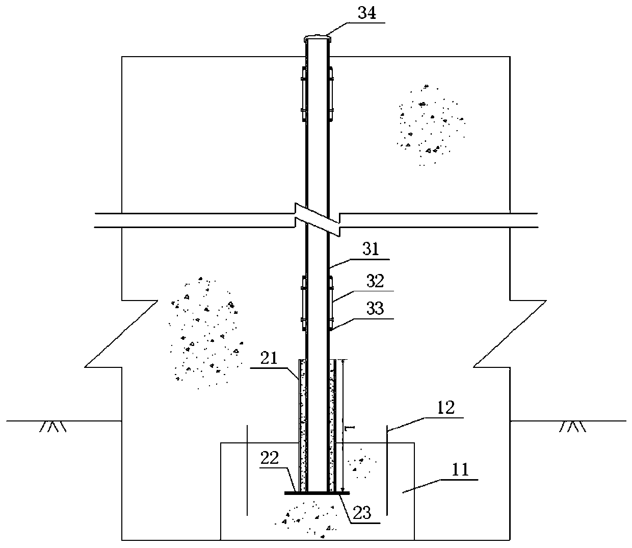
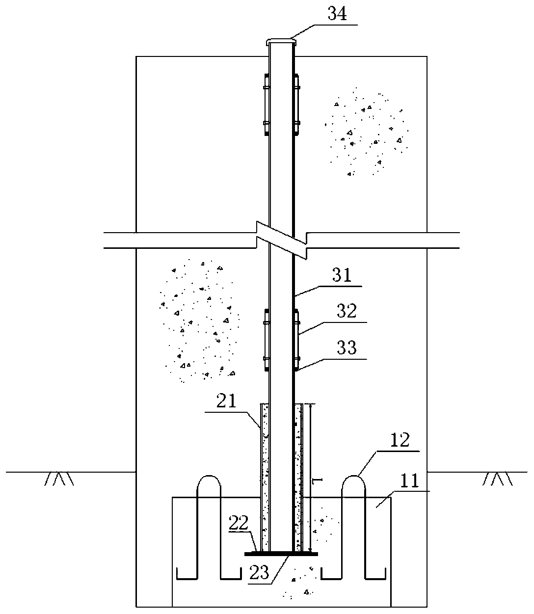
[0035] Such as figure 1 , figure 2 As shown, an installation device for inclinometer pipes in a concrete anti-seepage wall of the present invention includes several inclinometer pipes 31, galvanized steel pipes 21, and concrete heavy blocks 11. The bottom of the inclinometer pipes 31 is inserted into a galvanized steel pipe 21, the bottom of the galvanized steel pipe 21 is poured in the concrete heavy block 11. The inclinometer tube 31 is generally made of ABS material, the bottom is inserted into a galvanized steel pipe 21, and the inclinometer tube 31 is located in the middle of the galvanized steel pipe 21, and the inclinometer tube 31 and the galvanized steel pipe 21 are separated by cement mortar. layer backfill. The inclinometer tubes 31 are connected by connecting sleeves 32 , and the inner diameter of the connecting sleeves 32 is the same as the outer diameter o...


PUM


Abstract

The invention discloses an installing device and method for inclinometer tubes in a concrete diaphragm wall. The device comprises a plurality of the inclinometer tubes, galvanized steel tubes and concrete weight blocks, the bottom of each inclinometer tube is inserted into one galvanized steel tube, the bottoms of the galvanized steel tubes are poured into the concrete weight blocks, steel hangingrings are arranged on the concrete weight blocks, a crane is adopted to hang the concrete weight blocks, the galvanized steel tubes and the poured inclinometer tubes into a slotted hole of the diaphragm wall and slowly lower, the inclinometer tubes on the upper part are connected section by section in the lowering process, and meanwhile clear water is injected into the inclinometer tubes to assist sinking till the concrete weight blocks sink to the bottom of the slotted hole. The device guarantees that the bottoms of the inclinometer tubes are located at relatively stable positions, guarantees the accuracy and reliability of horizontal displacement monitoring of the diaphragm wall, and meanwhile, adopts a theoretical formula to deduce the length of the galvanized steel tubes, thereby being more scientific and reasonable.

Description

technical field [0001] The invention belongs to the technical field of safety monitoring of water conservancy projects, and in particular relates to an installation device and method for an inclinometer pipe in a concrete anti-seepage wall. Background technique [0002] Dams and embankments often use concrete cut-off walls for anti-seepage treatment. The horizontal displacement monitoring of the cut-off wall is usually a safety monitoring item that needs to be set up. bottom of the hole), using a movable inclinometer or a fixed inclinometer for observation. Since the cutoff wall is generally made of low elastic modulus concrete without a steel cage, the inclinometer tube cannot be fixed. In order to install the bottom of the inclinometer tube to the bottom of the slot in the cutoff wall, the method of adding water to the inclinometer tube to increase the pressure is mainly used at present. The method makes the bottom of the inclinometer tube sink into the bottom of the cut-...

Claims


Application Information

Patent Timeline
IPC IPC(8): E02B1/00E02B3/16G01C9/00G01C9/02
CPCE02B1/00E02B3/16G01C9/00G01C9/02
Inventor 邓成发吉顺文黄君宝施齐欢郑敏生于桓飞何耀辉李雪梅张婷
Owner ZHEJIANG INST OF HYDRAULICS & ESTUARY
Why Eureka
Eureka Blog
Learn More